repair of marine diesel engines - steps to change the piston
Introduction
Till now we have learnt about the various components of marine diesel engines including bedplate, crankshaft, crankshaft deflections, pistons, piston rings, manufacture of piston rings, piston ring clearances and methods of dealing with an overheated piston. Despite the best of efforts pistons do have a specific lifetime and one day it has to be replace no matter how much well maintained it is. In this article I will tell you the general steps on how to go about changing the huge piston of the main propulsion plant of the [ship](https://www.brighthubengineering.com/naval-architecture/13218-what-are-dynamic-positioning-vessels-and what-are-they-used-for/) namely a two stroke marine diesel engine.
Step of Changing the Piston
-
The spare piston always kept properly secured and lots of grease is applied to it to prevent against any kind of corrosion. Hence whenever it is required to be used as a substitute for the old piston which has to be removed, it is first cleaned up thoroughly to remove all that grease and the possible dust and dirt that have covered it up during its lonely stay at some bulkhead.
-
It is necessary to gauge the liner and the piston to check whether they are compatible with each other. This is may seem unnecessary to many engineers but this is worth the check.
-
Any possible leakage in the cooling water space is checked by using pressure test with water as the test liquid. It is not necessary to attain several times of the normal working pressure but approximately one fifth of the pressure above the normal working pressure should be sufficient to perform this test.
-
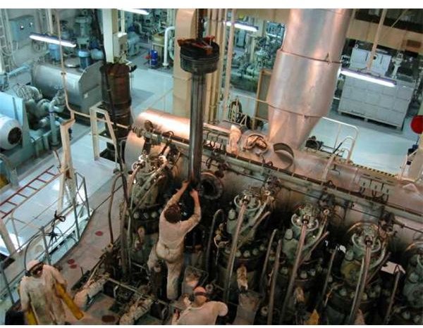
Initially do not insert the piston rings on the piston and lower it in the liner after securing it at the crosshead. The engine is then turned in the ahead direction using the turning gear and readings of piston clearance and guide clearances are taken at the tip and at the rubbing ring. The image below shows an engineer assisting the lowering of the piston into the liner.
-
The above readings are taken at the various angular positions of the crankshaft namely TDC, 30, 150, 180, 210 and 330 degrees respectively at the four diametrical positions of forward, aft and the athwartship directions.
-
These readings are recorded in a table which helps the engineers to check at a glance about the alignment of the piston vs. the cylinder liner bore.
-
The clearance volume also needs to be correct and for this the piston is brought to the TDC position again and the relative height of the piston with respect to the machined top surface of liner is noted.
-
After ascertaining about the correctness of the dimensions and clearance volume the piston is removed outside, fitted with the correct piston rings and lowered back again into the liner. The other parts are fitted as well in the correct order.
-
For the first 100 hours the new piston is not run on heavy oil but only on clear distillate fuel and that too on a light load which helps running in of the bedding of piston rings on the cylinder liner surface.