Decarbonization of Engines
Introduction to Decarbonization of Aux Engines
Decarbonization is an important part of the maintenance of auxiliary engines aboard ship.
It is necessary to protract the engines optimum working condition, ensuring efficient and safe running of these important auxiliaries.
This is an article in Marine Engineering and here we examine the methods involved in the decarbonization of aux engines – the power generators.
We begin with an overview of a typical four-stroke diesel engine used to drive the electric generators aboard ship.
Overview of A Typical Marine Auxiliary Diesel Engine
The generators are the powerhouse of the ship, producing the electricity to run the various pumps and equipment required for the main engine.
There are normally three diesel generators in the engineroom; two being used whilst in port, whilst at sea only one is usually required with one on standby; the third one available for maintenance or also standby.
The generators are run for a certain amount of hours before they require routine maintenance, the total hours of running being split between all three generators as evenly as possible.
To keep the engines in good condition, regular maintenance is required. This includes the decarbonization of components involved in the combustion system; namely the cylinder liner combustion area, the cylinder head and valve gear, and the piston/rings.
It is very important to have all the necessary spare parts that are normally required for decarbonization, as well as the right tools to carry out the removal of carbon from the combustion components.
Whilst I was serving my apprenticeship at Harland & Wolff Belfast as a marine fitter 45 years ago; I made a lot of my own tools. I still have some of these today (don’t think EBay would be interested though!)
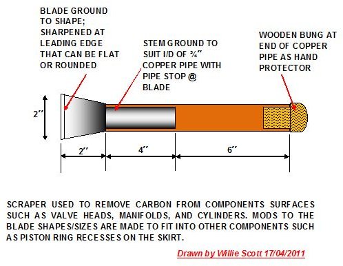
Among these tools, I had a few scrapers made from old mechanical saw blades, shaped to fit into a piece of ¾” copper pipe used as the handle. I made a few of these whilst at sea and carried them with me to the different ships. I think in today’s climate in airline security I would be stopped at check-in and the scrapers confiscated.
Anyway I diverge – a trait of retired old Irish marine engineers. I have included a couple of sketches below of the scrapers, as they are simply made and last forever.
There are also images of the modern flexi-drives, wire brushes, and flappers that make life much easier for today’s ships Engineer Officers.

.
Page 2 examines the decarbonisation of the main combustion components in more detail.
Decarbonization of Marine Diesel Auxiliary Engines
In a marine diesel auxiliary 4-stroke diesel engine the main components that are affected by the build-up of carbon are:
- Cylinder head combustion chamber.
- Exhaust valves and manifold.
- Upper cylinder liner at combustion space.
- Piston crown and piston rings.
We shall now examine the engine combustion components showing how the carbon is removed.
The Cylinder Head
Normally the combustion chamber is formed by the inverted bowl shape of the cylinder head that matches a domed shape of the piston crown, with there being many examples of combustion chamber designs. It is this inverted bowl space that becomes coated with carbon deposits as shown below.
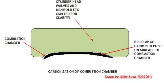
Once the exhaust valves, injectors, etc. have been removed from the head, the carbon is easily scraped off the surface of the combustion chamber. A rub with a wire brush then emery cloth removes the rest of the accumulation.
The Exhaust Valves and Manifolds
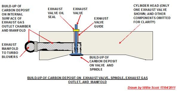
valves operate under very high temperature, being lubricated between the valve stems and the guides. There are oil seals on the stems, but these can wear allowing lube-oil to penetrate into the combustion chamber. This causes a build-up of carbon on the spindle and around the valve head. This is added to by the expulsion of the combustion gasses passing the valve to the turbo blower’s manifold.
These gases also leave a deposit of carbon on exhaust gas manifolds. If not removed, the carbon can impede the operation of the exhaust valve gear.
A sketch of these components is shown below.
The exhaust and inlet valves are removed (remember to match-mark the valves to their respective seats) and immersed in a tray of diesel to loosen the carbon from the stems and body. The stems can then be carefully cleaned. (I had an old penny coin with a notch cut out of it that I used for this purpose for many years, the material being softer than the stem caused no damage.) Remember, don’t use emery cloth on the stems; the stems are accurately ground to fit the valve guides and oil seals. When completed they are dried with a soft cloth and put aside for the next stage. During decarbonization of the cylinder head, I normally ground the inlet and exhaust valves into their seats.
Meanwhile the exhaust gas tract to the manifold also needs cleaning. This is done using a small rotating wire brush on flexi-drives that fit into a normal electric drill chuck; these get into all the wee nooks and crannies a scraper or conventional hand wire brush will miss. Final wash out in the diesel oil tray and a thorough blow out with compressed air and inspection with a small flexi light complete the decarbonization of this component.
- Upper cylinder liner combustion space
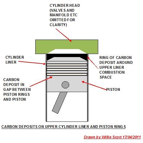
Combustion also leaves a “ring” of carbon around the cylinder liner combustion area. This gradually builds up and if not removed can impair the combustion efficiency. This accumulation must be removed before withdrawing the piston. This is usually carried out by scraping the excess away then using a “flapper” on a flexi drive to finish, care being taken not to remove any metal from the liner internal surface.
Piston and rings
Once the piston has been removed from the liner and connecting rod, the rings can be removed and immersed in the cleaning tray.
Excess carbon can now be scraped off the crown, finishing off with flapper attachment as above. Now is a good time to clean out the ring grooves, using a scraper only, ensuring the carbon deposits on the horizontal and vertical surfaces are completely removed. A thorough wash out with diesel oil then drying completes this decarbonization process.
A sketch of these components is shown below.
The rings are then cleaned and oil ring blown out with compressed air. Check the oil holes for “burrs” or loose slivers of metals. When I was serving my time, I spent a few months in the piston ring department of the engine works. Here we used a small rat-tail file to ensure all the burrs that are a result of machining were completely removed.
However, during piston/ring maintenance of both main and auxiliary engines at sea, I have experienced loose slivers of metals on new and used rings.
Now is a good time to check cylinder liner and piston ring wear, replacing the rings/liner as required.
A final check of all components for dirt and we are ready to rebuild the engine.
Remember to clean the cylinder liner seal ring landings and to use new rubber sealing rings on the cylinder liner, lubricating with soft soap or other recommended lubricants.
Use new cylinder head gaskets and exhaust/manifold gaskets. It is also a good time to replace the air start, relief, and fuel injection valves.
Always change the sump lube-oil and clean the filters after decarbonization of the engine; no matter how careful you are, some carbon will fall into the sump.
Record the piston ring/liner clearances along with any replacement components along with the hours run to date in the generator log book.
Webs Visited:
1. frontierpower: How long will a marine diesel last?
- marineinsight: Decarb of ships generators.
3. mandieselturbo: Genset decarbonisation.