Limits & Fits, GD&T Tutorial - Hole Basis Tolerance System or Shaft Basis Tolerance System
As a mechanical design engineer you may have to design a shaft or mating hole component or both. For such design assignments, you have to decide the GD&T limits and fits, and for deciding the limits and fits, you have to decide whether you want to go with the hole basis system or the shaft basis system. And for making such a decision, this article will be helpful.
Shaft and Hole Fits Basics
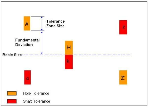
While dealing with shaft and hole, you will come across the three basic types of fits: clearance fit, transition fit, and interference fit or something in between these (like loose running fit, sliding fit etc.). From the GD&T limits and fits tutorial you already know that the shaft and the hole tolerance grades are represented like below:
Shaft Basis System
- Take the maximum size of the shaft as datum for the fit. That means, you have to take hole basic deviation class as h. (How? Look at the above picture. The minimum tolerance of the h grade is coinciding with the basic size).
- Now, decide the tolerance grade (or IT number, the number followed by the basic deviation, something like 6, 7 or 8) for the shaft depending upon the machining process.
- You should know the allowance (the minimum clearance or interference between the shaft and the hole) from the application of the shaft and hole. Add or subtract (for clearance or interference fits respectively) the allowance value from the shaft diameter to get the minimum hole diameter.
- Apply the shaft tolerance grade.
Hole Basis System
- Take the minimum size of the hole as datum for the fit. That means, you have to take hole basic deviation class as H. (How? Look at the above picture. The minimum tolerance of the H grade is coinciding with the basic size.)
- Now, decide the tolerance grade (or IT number, the number followed by the basic deviation, something like 6, 7 or 8) for the hole depending upon the machining process.
- You should know the allowance (the minimum clearance or interference between the shaft and the hole) from the application of the shaft and hole. Add or subtract (for interference and clearance fits respectively) the allowance value from the hole diameter to get the shaft maximum diameter.
- Apply the shaft tolerance grade.
Where to Use What
- For a standard manufacturing process where hole is manufactured by drilling, reaming, etc. and the shaft by turning, etc., go for the hole base system, because altering the hole diameter by a small amount is not possible for such cases, and on the other, shaft diameter can be varied.
- In the case where the shaft is used as a common mating part for a large number of holes or shaft diameter is fixed and hole diameter can be varied then it is better to go for shaft basis system.
Conclusion
GD&T limits and fits can be applied either by the shaft basis tolerance system or by hole basis the hole basis tolerance system. By and large, the hole basis system is most used in industry, unless there are multiple parts with holes are fitted with a single shaft.