Geometric Dimensioning Tolerancing Tutorial – GD&T Projected Tolerance in Engineering Drawings
Engineering drawing is the communication tool among the mechanical engineers in industry. The whole intent of an engineering drawing is communicated by means of figures and suitable symbols. It is very important that the drawing conveys a single meaning to all its users and here geometric dimensioning and tolerancing, or GD&T, plays an important role. How? We will discuss this in the next paragraph.
Why to Use GD&T?
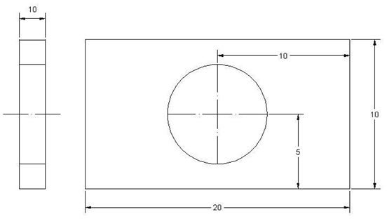
Say, you want to create a rectangular plate with a circular hole and for that created the drawing specifying the hole-centre and other dimensional details like below:
Now, with this drawing if you got a plate with a oval shaped hole with the centre at specified location, you should not be surprised as your drawing does not communicate the shape of the circle. By using GD&T in your engineering drawing, you can avoid such problems.
What is Projected Tolerance?
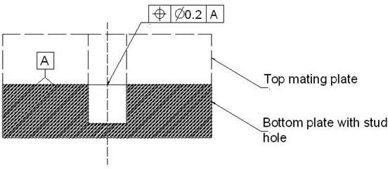
The projected tolerance is a GD&T modifier used for threaded and press fit holes in order to ensure the proper fitments of the mating parts by means of studs or bolts. Let’s see the following example:
Say, you have a plate with a hole in which a stud will be inserted. The projected portion of the stud will secure another mating plate. See the drawing of the bottom plate with thestud hole (top mating plate is in dotted line):
Now with only the positional tolerance of 0.2 specified in the drawing, the hole-axis of the bottom plate can be varied like below at the worst case:
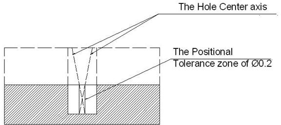
From the figure it is clear that if the stud axis follows the worst case then the stud may interfere with the mating plate. And for avoiding that interference specifying the projected tolerance in the drawing is required. The below figure will show how project tolerance will avoid such interference:
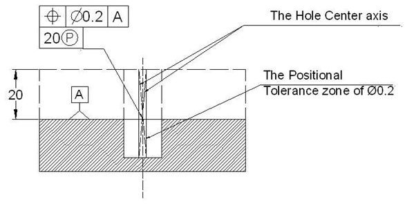
You can see projected tolerance of 20 has been mentioned in the drawing by separate frame below the previous GD&T frame. The meaning of the projected tolerance of 20 is the positional tolerance zone of 0.2 will extend by 20mm beyond the surface of the bottom plate. And by doing so, the variation of the axis has been reduced substantially as you can see from the figure above.
Conclusion
Geometric dimensioning and tolerancing or GD&T helps create more universally interpreted engineering drawings. The projected tolerance modifier is used for the long bolts or studs that secure two mating plates.