Hydraulic Pressure Intensifiers - How do They Work?
The Need for Hydraulic Intensifiers (or Boosters)
In most of the hydraulic machinery used, the usual pressure of 80 to 100-psi may not be sufficient to operate certain spool valves and other mechanisms. To cater to the need for a high pressure requirement for a comparatively short period of time, pumps and accessories are definitely not the solution. But the substitute can be hydraulic intensifiers which can increase the pressure from 100 psi to 40,000 psi, using small volumes of fluid.
There are different types based on the medium of hydraulic fluids used and the number of strokes used to intensify to the desired pressure. They are single-stroke, differential cylinder intensifiers, oil-oil intensifiers, air-air intensifiers, and oil-air intensifiers. Recent developments are so vast that huge pressures are achieved by using combinations of the above types.
How Hydraulic Intensifiers Work
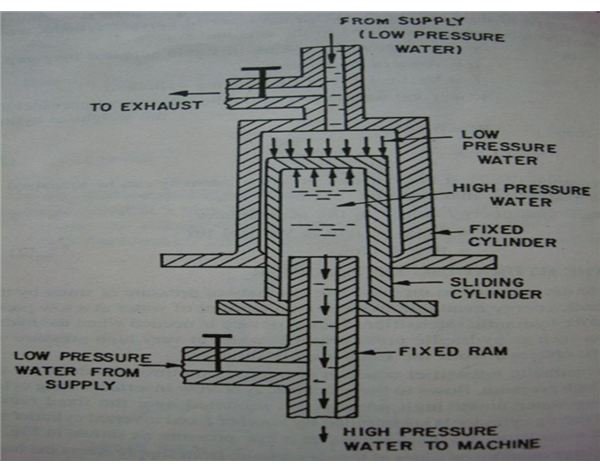
A hydraulic intensifier is a device which is used to increase the intensity of pressure of any hydraulic fluid or water, with the help of the hydraulic energy available from a huge quantity of water or hydraulic fluid at a low pressure. These devices are very important in the case of hydraulic machines, mainly hydraulic presses, which require water or hydraulic fluid at very high pressure which cannot be obtained from the main supply directly.
There are three main parts in the hydraulic intensifiers to be noted. They are
- Fixed ram,
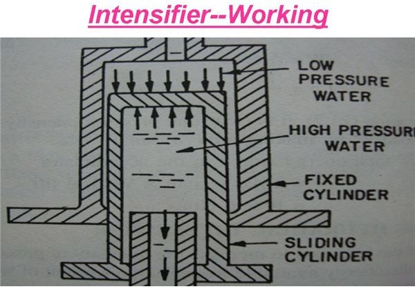
- Hollow inverted sliding cylinder,
- Fixed inverted cylinder.
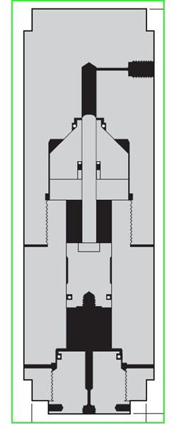
A hydraulic intensifier consists of fixed ram through which the water, under a high pressure, flows to the hydraulic machine. A hollow inverted sliding cylinder, containing water under high pressure, is mounted over the fixed ram. The inverted sliding cylinder is surrounded by another inverted fixed cylinder which contains water from the main supply at a lower pressure.
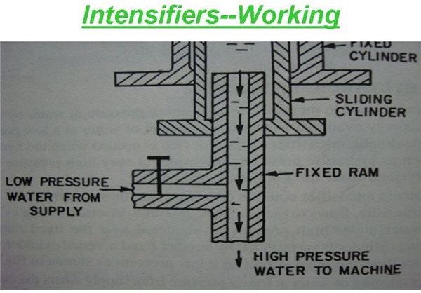
A large quantity of water at a low pressure from the supply enters the inverted fixed cylinder. The weight of this water presses the sliding cylinder in the downward direction. The water inside the inverted sliding cylinder gets compressed due to the downward movement of the sliding cylinder and its pressure thus increases. This high pressure water is forced out of the sliding cylinder through the fixed ram, to the hydraulic machine.
Working and System Description of a typical Hydraulic Intensifier:
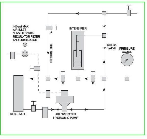
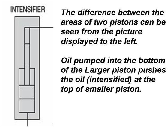
A typical hydraulic intensifier of 150,000 psi has its pistons designed to the ratios of 10 to 1. The intensifier assembly has two pistons of two different diameters. The piston which is at the lower end is of larger diameter than the piston which is at the top of the assembly. These pistons have very fine clearances to move within the intensifier body. The material of construction of the pressure holding parts are 4340 alloy steel or its equivalent. These parts are properly heat treated for its use at higher pressures. It is mandatory for the operator to use only non-corrosive hydraulic fluids inside the system, as corrosion of these components may lead to increase in clearances and thus a drop in the equipment’s performance. The piston rod has one or more packing, which is suitable for withstanding high pressures and thus housed in a stuffing box.
The system has an air-operated hydraulic pump, for which air is supplied through a pressure regulator, filter, and lubricator. Typical air pressure values for these pumps are 80 to 100 psi. The air pump draws the hydraulic oil from the reservoir and pumps it to the intensifier circuit which has manual valves and pressure gauges. The pump’s usual discharge pressure is of the order of 16000 psi. The air-operated pump delivers oil on to the top piston of the intensifier, with the valves, “A” and “B” shut. This pressurized oil pushes the top piston of the intensifier down and thus making it rest in the downward stroke. With the valves “A” and “C” closed, the pump delivers oil to the larger diameter piston which is at the bottom of the intensifier stroke. This pressurized oil pushes the piston up and thus the oil on top of the smaller piston gets compressed and its pressure gets intensified.
You may be wondering how an oil pressure of 16000 psi can push a piston to deliver an oil pressure of 150,000 psi. It is the basic idea of Pascal’s law and the difference in areas of the two pistons. Even though the oil is at 16000 psi, the area on which it acts is huge when compared with the area of the smaller piston. It is this area upon which the pressure is acting that enables the smaller piston to intensify the pressure to 150,000 psi.
Image & Content Credits: