Inductive Transducers or Inductive Linear Transducers
Inductive Transducers
The inductive transducers work on the principle of the magnetic induction of magnetic material. Just as the resistance of the electric conductor depends on number of factors, the induction of the magnetic material depends on a number of variables like the number of turns of the coil on the material, the size of the magnetic material, and the permeability of the flux path. In the inductive transducers the magnetic materials are used in the flux path and there are one or more air gaps. The change in the air gap also results in change in the inductance of the circuit and in most of the inductive transducers it is used for the working of the instrument.
There are two common type inductive transducers: simple inductance type and two-coil mutual inductance type. Both have been described below along with their circuits.
- Simple Inductance Type Inductive Transducers
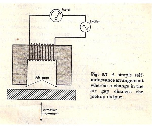
In the simple inductance type of the inductive transducers simple single coil is used as the transducer. When the mechanical element whose displacement is to be measured is moved, it changes the permeance of the flux path generated by the circuit, which changes the inductance of the circuit and the corresponding output. The output from the circuit is calibrated directly against the value of the input, thus it directly gives the valve of the parameter to be measured.
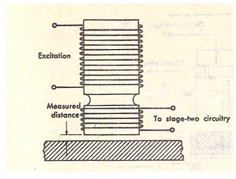
The figure 1 below shows the single coil inductive circuit. Here the magnetic material is connected to the electric circuit and it is excited by the alternating current. At the bottom there is another magnetic material that acts as the armature. As the armature is moved, the air gap between the two magnetic material changes and the permeance of the flux generated by the circuit changes that changes the inductance of the circuit and its output. The output meter directly gives the valve of the input mechanical quantity.
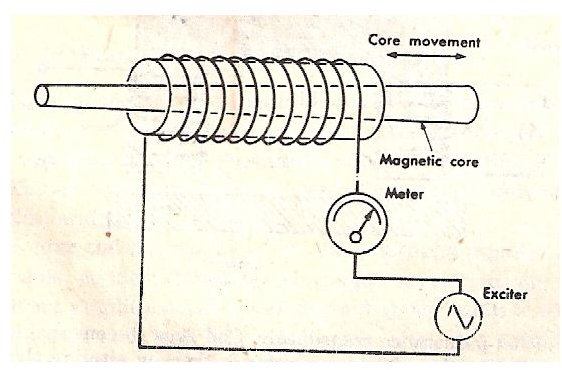
In the figure 2, coil is wound around the round hollow magnetic material and there is magnetic core that moves inside hollow magnetic material. In the above circuits the change in the air gap or the change in the amount of the magnetic material in the circuit can be used to produce the output proportional to the input.
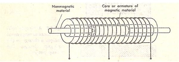
Another arrangement of the coils is shown in figure 3, where two coils are used. In this circuit the movement of the core changes the relative inductance of the two coils and over all inductance of the circuit. This system is used in the devices along with the inductive bridge circuit. In this circuit the change in the induction ratio of the two coils provides the output proportional to the mechanical input.
In the above arrangements the supply of the current and the output is obtained from the same coil or circuit.
Simple Inductance Type Inductive Transducers
- Two-Coil Mutual Inductance Type Inductive Transducer
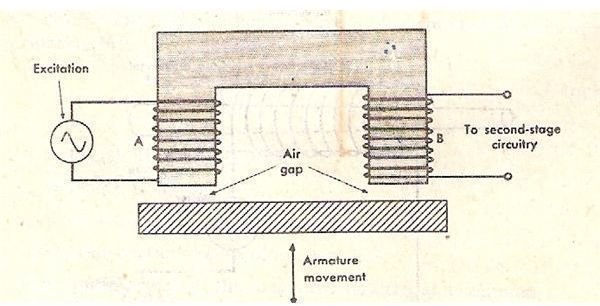
In the two coil arrangement there are two different coils. In the first coil the excitation is generated by external source of the power and in the second coil the output is obtained. The output is proportional to the mechanical input.
As shown in the figure 4 below, A is the excitation coil and B is the output coil. The inductance of the output coil changes due to change in position of the armature which is connected to the mechanical element whose motion is to be measured. As the armature position changes, the air gap between the fixed magnetic material and the armature changes. The arrangement shown in figure 5 also works in the similar manner.
Two-Coil Mutual Inductance Type Inductive Transducer
Reference and Images Courtesy
- Book: Mechanical Measurement by Thomas G. Beckwith and N. Lewis Buck, Oxford and IBH Publishing Co. Pvt Ltd.