Boiler Fixtures and Fittings
Boiler Auxiliaries
Introduction
This is another article in the current series on power plants. Here we examine the important role played by the auxiliary components in a power plant, which I have split into two sections, boiler auxiliaries and steam turbine auxiliaries. In this article we will examine a two drum water-tube oil fired boiler. The next article will cover the steam turbine auxiliaries.
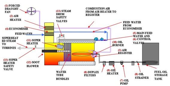
I have omitted the refractory and downcomers from the boiler drawing for clarity and have laid the main components out in their different systems such as feed water or combustion air system and have numbered the items cross referencing them to the relevant sketches.
Please refer to the relevant sketch when reading the text on components.
Combustion Air System
1. Forced Draught Fan
The forced draught fan draws air through a set of filters from the top of the boiler room and discharges it through ducting into the air heater.
2. Air Heater
The air heater is situated in the flue gas ducting from the boiler and transfers some of the heat from the hot gasses to the combustion air, heating it before it is ducted to the air register.
3. Air Register
The heated air is now ducted into the furnace register, a circular cowling which swirls the air blowing it into the furnace combustion area at an air ratio of between 10 and 20%.
Boiler Feed Water System
The boiler feed water is a mixture of condensate and make-up water. This is fed to the boiler by the boiler feed pump located in the turbine hall.
4. The Economiser
The economiser heats the feed water on its way back to the boiler.
This is another heat exchanger situated in the exhaust gas ducting and the feed water passes through the tube nest which transfers the heat from the surrounding hot gasses
5. Boiler Feed Control Valve
The feed water has now reached the valve which controls the supply of feed water to the top drum. This valve opens and closes as the steam pressure and flow varies.
6. Boiler Feed Check Valve
The last valve before the drum, this is a non return valve used to isolate the feed water supply to the boiler.
Fuel Oil System
7. Fuel Oil Pump
The fuel oil is drawn from the storage by the pump and tank through a couple of screens and pumped into the fuel oil heater.
8. Fuel Oil Heater
The oil will already have been heated in the storage tank but is still very viscous. It is heated to a high temperature.
9. Fuel Oil Duplex Filters
From the heater the oil is pumped through the duplex fine mesh filters which can be changed over and isolated for cleaning. These filters run very hot and must be allowed to cool down before cleaning.
- Fuel Oil Burner
This is located in the air register and atomises the fuel spraying it into the furnace. The combustion air is swirled in around the oil which is ignited and burned in about 20% excess air.
Steam System
The steam is generated by boiling the water in the water tubes which run between the water drums and the steam drum. Wet steam exits from the steam drum and is piped to the superheater.
11. Steam Superheater
This is an enclosed nest of pipes located in the hottest section of the exhaust gasses, usually to the underside of the steam drum. From here the superheated high pressure steam is piped to the superheater header and into the turbine hall, where it enters the HP stage of the steam turbine.
12. Sootblowers
There are numerous sootblower units located around the water tubes economiser and air heater tubes.
These are basically a long perforated pipe which rotates spraying steam or compressed air onto the boiler tubes removing the coating of soot deposited by the combustion gasses.
They are controlled to operate periodically maintaining the boiler water tube, economiser, and heat exchanger heat transfer efficiency.
13. Safety Valves
In order to protect the boiler from overpressure there are two safety valves fitted to the steam drum outlet piping and one safety valve fitted to the superheater outlet header.
The superheater safety valve is always set to lift before the two steam drum valves in order to prevent the superheater from collapsing due to lack of steam flow. (If the drum valves lifted first this would starve the superheater of steam.)