How to Make a Simple Telephone Ring Amplifier
Landline telephones are often not loud enough to be heard in adjacent rooms. Especially if the area happens to be surrounded with lot of commotion. The same may be true with telephones in workshops where the noise from heavy machinery can totally prevent one from hearing the ringing.
However, if with a small inexpensive circuit, the audio or the ring from the telephone is amplified externally, it can make the sound reach to greater distances. One such telephone ring amplifier is described here. Let’s learn how it functions.
Circuit Descriptions
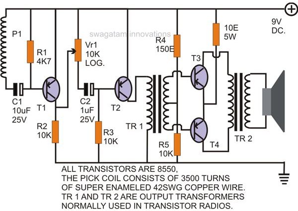
The circuit is comprised of just a few ordinary components and may be built within an hour. The pick-up coil is the only component that’s difficult to build at home so it either can be procured ready made (if available) from the market or preferably made to order.
The pick-up coil actually behaves like a big antenna and therefore needs to be positioned close to the telephone instrument. The minute electromagnetic waves emanating from the telephone while it rings are induced into the pick-up coil and get “condensed.”
The AC component from the above signal passes via C1, is sensed by T1, and is amplified to a certain degree across R2.
This low degree amplified audio is allowed to pass through a variable resistor VR1 whose setting determines the amount of signal that may be transferred into the next stage. Thus here V1 acts as a volume control.
The regulated signal from VR1 is injected into the base of T2 via another DC blocking capacitor C2. C2 makes sure that the DC supply voltage through R2 is well blocked from reaching the base of T2.
T2 thus conducts only with the received telephone “ring” frequency at its base. The collector of T2 instantly responds and induces fully supply voltage corresponding to the received frequency into the primary winding of the audio input transformer TR1.
Just like supply voltage transformers this input transformer also behaves the same way and steps-up its primary frequency to a much higher level at its secondary winding.
Two transistors T3 and T4, configured as current amplifiers are positioned at the output of the above transformer to further amplify the signal to a level suitable for driving an output transformer.
Just as TR1, the output transformer TR2 further steps up the amplified signals from T3 and T4 to the maximum, enough for reproducing the telephone ring loudly over a loudspeaker connected at the secondary of TR2. Therefore we are finally able to hear the amplified version of the rings from this telephone ring amplifier circuit.
References
-
Authors own experience.
Images drawn by the author.