How to Build an Electronic Mosquito Repeller Circuit

Simple Ultrasound Generator
These tiny blood sucking vampires will be back again leaving behind lot of itches and swellings. The constant “swarming” and “buzzing” around us often ends up becoming the worst nightmare … when ultimately we decide that “enough is enough” and seek revenge.
Using mosquito nets to guard yourself from mosquitos looks pretty sensible and is an easy way to evade them, however some of you may complain of suffocation- being stuffed inside a netted cage.
Chemical and fume based alternatives are effective, but the emissions that are intended to be harmful for these insects can also prove toxic to our health in the long run.
Image Credit: Photobucket.com
Although controversial, an ultrasound electronic mosquito repeller device may be worth trying to see whether it can really effectively do away with these unwanted guests in your household.
The device is based on the fact that every creature may be sensitive to a particular audio frequency and may find it distasteful. Research has proven (though not to everyone’s satisfaction) that the resonating, “buzzing” frequency of a mosquito’s wings can inflict a lot of confusion and chaos in the “minds” of these little devils, which finally may force the group to quit the area.
If you go by the skeptics, you may after all decide against building this project. However, since this particular experiment will cost you no more than a dollar or two, you may as well give it a try. If the circuit is well optimized, and if you manage to find the exact frequency to nauseate or confuse mosquitos in your area, who knows? You might succeed in hitting the “bull’s eye.”
Circuit Description
Through many of my articles I have already discussed astable multivibrators (AMV) and their mode of functioning. These can be built around the ubiquitous 555 IC or using CMOS ICs like 4093 or 4049.
However an AMV using a couple of transistors and a few other passive components is a better alternative simply because it costs less, it’s easy to build, and the generated waveform may be easily distorted as desired by just altering the balance of the two halves of the circuit. The AMV here is being used to generate the required vibrations.
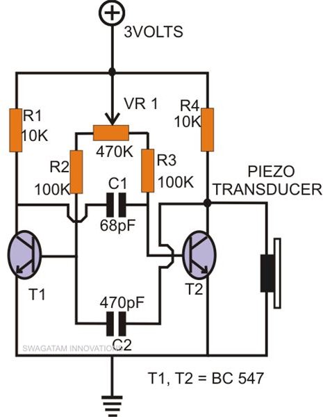
Referring to the figure, it’s almost immediately visible how the circuit is configured – T1 and T2 alternately start conducting indefinitely immediately after the power is switched ON.
The alternate switching actually take place due to capacitors C1 and C2, which alternately get charged and discharged, in fact the capacitors and the transistors compliment each other to sustain the oscillations.
The frequency of oscillations particularly depend on the value of the base resistors R2 and R3 and also definitely C1 and C2. To generate a perfect square, we would require keeping the balance of the two halves as equal as possible by selecting identical components for the two halves.
However for the present design we are interested in getting a non-symmetrical waveform that can typically give rise to abrupt high frequency pulses. That’s why the chosen components differ in their values. You may want to optimize its performance further by adjusting VR1.
A value anywhere near 20 kHz can prove effective. This range may be “invisible” to our ears, but it may well rattle these tiny raiders. Such a waveform is also said to be more suitable in creating a lot of uneasiness among the mosquitoes.
The generated frequency drives a piezo electric buzzer directly connected across T2.
The circuit will require just 3 volts, which may be supplied using a button cell that should last ages.
Although I have tested this electronic mosquito repeller circuit and had to satisfy myself with some mixed results, it will quite depend on how much effort you put in optimizing the control and recognizing the type of mosquitoes in your area to make it work successfully.