Build a Moving Message Display Circuit Using Discrete Components
Making Messages Move
A moving message display or a scrolling message display is an excellent method of communicating information. The smooth sailing effect of the alphabet or the characters is not only very pleasing to watch, but also more information becomes accessible through a small passage.
If you are not interested in scrolling messages with the present circuit, then perhaps you may simply use it with colorful LEDs to create a spectacular and very innovative display of moving arrays of LEDs.
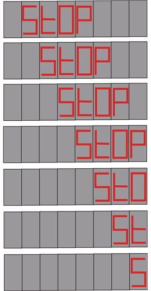
Here we study one such simple idea exclusively developed by me and see how we can make the word “STOP” slide over an eight slot display panel.
Circuit Description
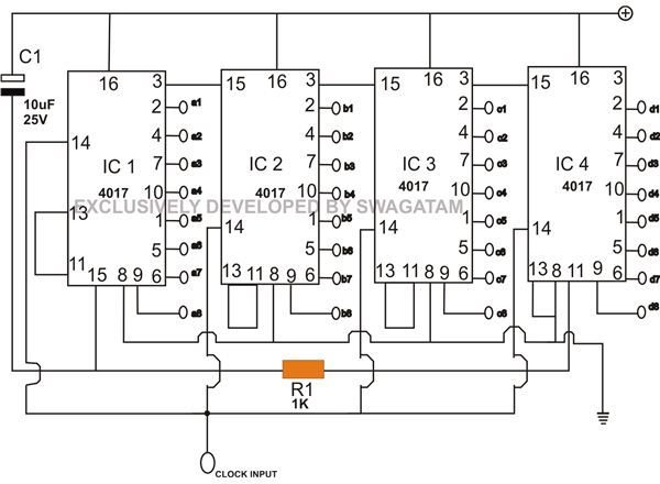
Again the versatile workhorse IC 4017 comes to our aid and helps to make the project look much simpler.
You may refer to the article here to get a comprehensive overview of the IC 4017, and it will also help you to understand the present circuit better.
Looking at the schematic we see that four of the above ICs are connected so that they conduct in tandem. Each IC handles a single alphabetic character and is responsible for shifting it sequentially through the entire length of the display panel (8 slots).
For example, the outputs of IC1 are connected to the each individual display (total 8 displays) sequentially so that its “running” outputs illuminate only the letter “S” of “StOP”. Similarly IC2 will do the same as IC1 but with the letter “t”, IC 3 will sequentially light up the letter “O” and IC4 will “chase” the alphabet “P”.
As explained, the above operations will happen exactly in tandem, i.e. the letter “t” will appear after “S” has jumped one digit – “O” will appear after “t” has moved a slot ahead and finally “P” will show up, creating a perfect display of the word “Stop” sailing/cycling smoothly over the entire length of the panel.
Let’s inspect the circuit more precisely:
Initially when power is switched ON, C1 resets the whole circuit so that pin #3 of all ICs becomes high (first pin out of the individual sequences).
At this very instant the high logic of pin #3 from IC1 holds pin #15 of IC2 and keeps it locked, similarly pin #3 of IC2 “freezes” IC3 and so on.
However in response to the input clocks, the moment IC1’s output shifts from pin #3 to the next sequence (pin #2), it releases IC2 from the binding.
Therefore as the output of IC1 proceeds from pin #2 to pin #4, IC2’s output jumps from pin #3 to the next sequence @ pin #2, releasing IC3 from the shackles, the process continues until IC4 also starts moving in sequence.
Since IC1 was the first to begin, its output sequence reaches its last pin out #11 first in the lot and latches with its pin #13 and “freezes”, next one to follow the procedure is IC2, then it’s the turn of IC3 and finally IC4.
However, IC4’s pin #11 is connected to pin #15 of the IC1, simply means that the moment IC4’s pin #11 reaches logic high, it resets IC1 and the whole sequence. The circuit position reaches its initial status and the cycle repeats all over again.
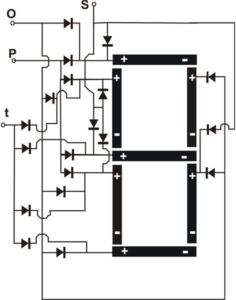
The adjoining diagram of a classic LED advertising display illustrates the wiring connections required to build the scrolling word “StOP” as discussed in the article as an example. (Click image to enlarge.) All diodes are = 1N4148.
A single display slot diagram is shown here, consisting of separate inputs for each portion of the alphabet of the word “StOP”. You will need to build eight such identical units. Since IC1 is handling the letter “S,” all the relevant letter inputs from the eight displays will go to the outputs of IC1 sequentially from right to left. Similarly all the “t” characters should be integrated with IC2 in the above manner and so on. The wiring is complicated, so it definitely will need to be done over a well-designed PCB.
Remember each segment of the display “8” can be built using four RED LEDs in series, but also remember to make all the LED negatives or the cathodes common and connect them to the negative side of the power supply.
Also since each IC is responsible for controlling a particular letter, bigger words can be selected by appropriately adding more ICs in the circuit. If you want to increase the length of the display or the number of slots, then you will need to cascade each IC stage as explained HERE.
To drive the clock input of this circuit you may incorporate any of the following oscillator/flasher circuits:
Using transistors
The present circuit should be operated through a regulated, stabilized power supply between 5 to 12 Volts.