How to Build a Versatile 0 to 12 Volt Adjustable DC Power Supply Unit
Foreword
Building the proposed circuit of 0 to 12 volt adjustable DC power supply is so simple that it may be even assembled even by a any electronic noob within half an hour. Moreover, the maximum output voltage may not be restricted to just 12 volts, rather can be extended up to 32 volts (continuously variable) by just modifying the transformer ratings appropriately. The whole operation becomes amazingly simple just due to the presence of this outstanding IC - LM 338.
The chip is simplicity by itself. It has just three leads, so confusion is reduced emphatically. Everything is built-in- just attach a couple of passive components to its pin-outs and you start producing the desired output voltages right away from it.
Before moving into the actual circuit description let’s first discuss a few of its design characteristics:
- 7 Amperes instantaneous peak current handling capacity
- 5 Amperes of regular and continuous current delivering capacity
- Output adjustable from as low as 1.2 volts up to 32 volts DC
- Excellent line and load regulation, typically 0.005%/volt and 0.1% respectively
- Built-in safe area protections from short circuits, overloads etc.
- Output current not affected by the chip’s varying case temperature
Circuit Description
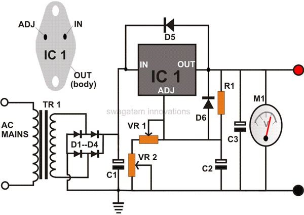
Referring to the figure we find the construction to be pretty straight forward. Let’s analyze the function and the importance of the various components involved around the IC LM 338 through the following discussion:
Step down transformer TR1 brings down the AC mains to the required level, the bridge diode circuit rectifies it, and capacitor C1 does the necessary filtering. The clean DC thus obtained is fed to the IC 338 configuration for further processing.
Capacitor C3, which is preferably a tantalum capacitor, acts an effective by pass for the unwanted residual AC signals,
C2 is included to enhance ripple rejections. It eliminates all possibility of any ripple amplification at the output when voltage is increased through effective by-passing of the small ADJ terminal ripple content. As above a solid tantalum capacitor is more suitable here due to its low impedance characteristics even at relatively higher frequencies.
Resistor R1, which is the current defining component, should be connected as close as possible to the IC’s lead terminals. Although the IC is equipped with an excellent load regulation feature, connecting R1 close to its leads terminates line potential drops improving load regulation efficiency.
The diodes D5 and D6 also perform important functions. In case the output capacitor C3 is accidentally short circuited by the connected load, it may inflict a high reverse current surge to the internal circuitry of the IC. D5 efficiently diverts the surge and helps avoid possible damage to the IC from the spikes generated by the discharging capacitors. D6 is kept to tackle discharge surges from capacitor C2.
The voltage is varied through a combination of two potentiometers VR1 and VR2. The inclusion of two potentiometers may look a bit unusual, however using two controls enables acquiring wide output voltage ranges and discrete calibration settings of the unit, thus making it more efficient and versatile.
Parts List
You will require the following parts to build the proposed circuit of the 0 to 12 volt adjustable power supply unit:
All resistors are 1/4 watt, CFR, 5% unless otherwise stated.
R1 = 120E
VR1 = 10K
VR2 = 4K7
C1 = 2200uF/50V
C2 = 1uF/50V, TANT.
C3 = 10uF/50V, TANT.
D1——D6 = 6AMP, 300V
IC1 = LM 338, TO-3
TR1 = 25-0-25V, 5 AMP. CENTER TAP NOT USED
HEATSINK = “C” CHANNEL, TO-3
M1 = VOLTMETER, 0-50 VOLTS