NAND Gate Circuit Designs You can Build - Flasher, Set/Reset Latch, Timer.
Simple Logic Circuits
Building circuits using CMOS gates can be great fun. These devices respond only to fixed logic levels and their outputs too respond in the same way. With them the results obtained are either a complete “yes” or a complete “no.” Thus, designing circuits using logic gates becomes much simpler compared to the linear ICs which may require complicated calculations.
If we take the example of a NAND gate, we find that it has two inputs and one output. According to its truth table a NAND gate may be configured into many different circuits through systematic optimization of its following input commands:
ONE INPUT—OTHER INPUT—OUTPUT
-———1——————1——————0—–
-———1——————0——————1—–
-———0——————1——————1—–
-———0——————0——————1—–
-
Positive voltage to both the inputs produces a negative voltage at its output,
-
Negative voltage to both the inputs produces a positive voltage at its output,
-
And if their two inputs are subjected to opposite voltages (one input at negative and the other one at positive), the output will remain fixed with a positive output.
It is important to note that an input of a CMOS gate should always be assigned to a particular logic level and should never be kept open at undefined logic levels, in simple words; the inputs at any instant should remain connected either to a positive voltage level or a ground (negative) level.
Let’s study how to build some simple circuits using NAND gates. The circuits may look simple, but they have huge application potential.
Practical Circuits Using NAND Gates
Here we will use the very versatile IC 4093 which is comprised of 4 NAND gates (Schmitt Trigger) and see how we can wire them up into a few amazing, yet simple circuits.
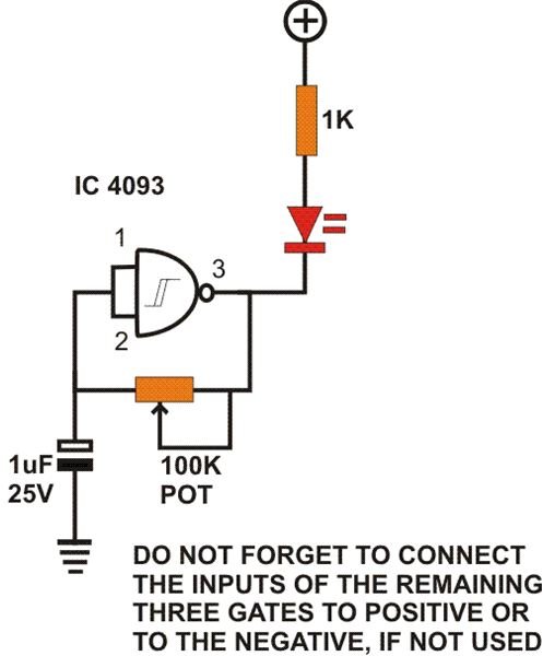
Oscillator: You will need just a resistor and a capacitor to build an oscillator from these gates. As shown in the figure, the configuration is pretty simple and its frequency may be adjusted by either altering the value of the capacitor or the resistor. Thus, we see that by suitably altering their values we may generate frequencies up to MHz levels or lower it to an extent where it may simply be used as a lamp flasher. You may build 4 discrete flashers with individual flashing rates, using a single IC 4093. You may replace the resistor by a pot to make the oscillations continuously variable as desired and use this circuit for flashing LEDs.
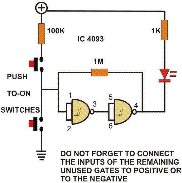
Set/Reset Latch: By connecting a couple of NANDs and the same number of switches, we can convert it into a nice little set/reset latch circuit. Pressing S1 toggles the whole circuit so that the output produces a positive voltage, conversely pressing S2 produces just the opposite result, i.e. the output shifts to produce a negative output. The configuration sustains its particular position or latches permanently, until it receives the next command from one of the switches.
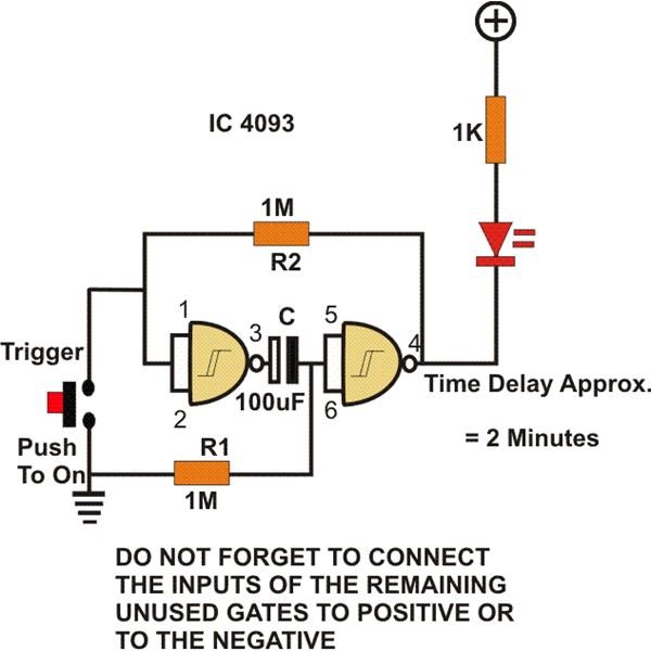
Timer: You will need just two of these gates and a few other passive components to construct a fine multipurpose timer circuit. Looking at the figure, initially because of the resistor R1 and R2, the whole system remains stationary, maintaining a logic high output. When S1 is pressed, the input of N1 is forced to ground, instantly inverting its output to logic high. This immediately charges C, forcing this time the input of N2 to become high and consequently its output to go low. The whole configuration now changes state. Meanwhile, C slowly starts discharging through R1 and after a period of time depending upon its own and the value of R1, gets fully charged. This retracts the positive from N1’s output and stops it from reaching N2’s input. N2’s output reverts, switching the circuit back to its original condition.