Why Buy a Single Ended Tube Amplifier When You can Build One?
Introduction
The fact is rather difficult to digest: vacuum tube amplifiers are more efficient in producing high fidelity music output compared to the transistorized or even some of the modern linear IC amplifiers.
Especially when it comes to the processing of high input frequencies, modern equipment tends to get a bit twitchy. Comparatively, vacuum tube amplifiers are much cleaner when dealing with high frequencies, and mind you, a music signal is always full of them.
Probably, that’s the reason why many audiophiles and music fanatics will even today try to grab a Hi-fi rig involving a tube amplifier, while most of us may quite consider them totally obsolete and a story of the past. People who have used vacuum tube audio amplifiers greatly appreciate their outstanding performance, perhaps because of the sound quality still lingering in their ears.
In this article we discuss how we can build, instead of buying, a simple single-ended tube amplifier. We’ll also talk about an interesting configuration that would integrate old with new. How about embellishing the proposed 6-watt tube amplifier circuit with a couple of modern amenities? A Hi-fi double tetrode music amplifer geared up with active tone controls and graphical LED level indicators will certainly spice it up.
Circuit Description
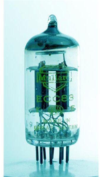
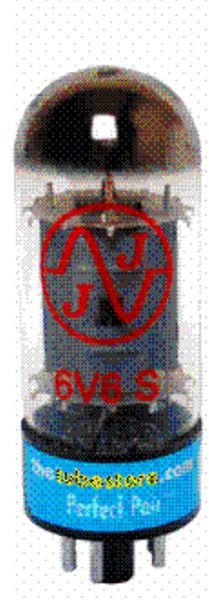
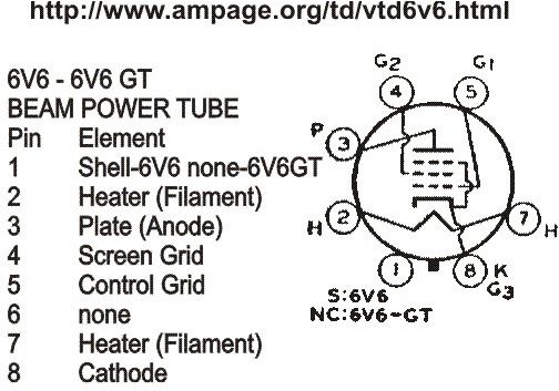
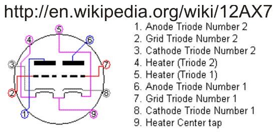
The amplifier is built around Mullard’s double tetrode ECC83 tube and beam power 6V6 output tubes.
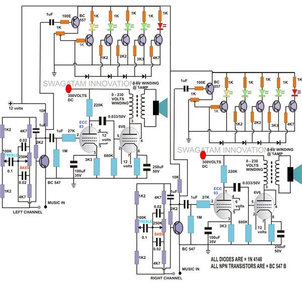
The adjoining circuit diagram shows a full fledged stereo version of the amplifier, while the following circuit description of a single channel will make the whole concept pretty clear:
The circuit incorporates a resistive input with R1 maintaining a link between the grid of T1 and ground, irrespective of the input conditions, and helping to create a low pass filter configuration in conjunction with ECC83’s internal Miller capacitance. This eliminates the entry of high frequency RF disturbances into the circuit making it as quiet as possible to stray frequencies.
R2 is used to provide the required biasing to ECC83, it’s kept in the path of the appropriately calculated load-line voltage of 300 volts.
The amplified signal from the input stage is coupled to the output stage via coupling capacitor C1 and further amplified by the driver stage consisting of the tube 6V6 and the associated components.
To match the driver stage output with the external 8 Ohm speaker, a matching output transformer becomes imperative.
Here, the driver stage impedance of around 5K Ohms needs to be matched with the speakers 8 Ohms. An ordinary 0-6V/230V/500mA transformer will do the job very nicely.
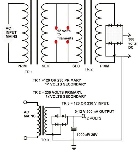
The transformer required to produce the rather unusual voltages for powering the whole unit may be difficult to obtain in the present world.
Therefore, here we wire up two normal transformers to get the desired sets of voltages. The configuration is pretty straightforward and the relevant power outputs become easily obtainable by using two general purpose transformers.
We have purposely employed a separate power supply for the tone control and the LED circuit to avoid messing up the high voltages involved with the tube power supplies.
Tube Socket - Fixing Instructions
Unlike modern electronic parts, a tube can never be soldered directly over a PCB simply because tubes are prone to electrical and mechanical damage in the course of time and may need replacements. We need to have an easy access to this, so that removing a faulty tube and replacing it with a fresh one doesn’t get messy. Fixing tubes over tube sockets thus becomes imperative just for the above reasons. However, the sockets are quite intricate devices that need some care while fitting them. Ideally the following points should be observed to make their assembly flawless.
A tube should never be soldered from the track side but from the normal component side.
Do not apply too much heat or do not linger with the soldering process, as that would allow excessive solder to flow inside the tube socket holes. This would render the socket totally useless because then the tubes can’t be inserted into it and also the spring action of the slots would be jammed.
Contradictorily, if you don’t solder the pins with adequate heat and solder, the joints may crumble in the due course and result into a dry solder.
The best way to optimize this would be to insert a fused or damaged tube into the socket first and then solder the pins. Now, since the holes are tightly occupied by the tube pins, no solder can get in and you may feel free to continue the soldering process with complete leniency.
Its always a good practice to mount the sockets tightly flush over the PCB surface so that the assembly is uniform and the tubes don’t find themselves tilted or inclined which may affect proper contact of the tube pins with the socket and the PCB.
A slight manipulation may be required with the alignment of the socket pins and the PCB holes. Do them carefully and do not force them into the socket. If the pins are slightly bent, carefully adjust their alignment with the PCB holes using a metallic pointer or a screw driver until it just eases itself into the drillings.
Please visit here to get a detailed information.
Active Tone Controls And LED Level Indicator
In the diagram above, we see that music input is applied to a simple yet effective bass/treble circuit which is in its most basic and standard configuration. At 100 Hz, it will provide a bass boost of about 13 dB and a cut at 11 dB. For high frequencies (above 15 KHz), the treble boost will be typically of 10 dB with a cut at 11 dB. P1 sets the bass level, whereas P2 fixes the treble response. The processed music simultaneously enters the tube amplier section and the LED indicator section for further amplification and level indication respectively.
The circuit of the LED level indicator is pretty basic and can be simply understood by looking at the schematic. Here, the transistors conduct in sequence as the input volume rises. The series diodes and the base resistors together make it sure that the transistors are biased and the LEDs switch ON one after the other as the music volume rises to produce a perfect push-pull effect to the LED lighting sequence.
Construction is very simple and may be finished within a couple of hours. Except for the tubes, all the parts are regular types and may be assembled quickly over a large piece of a general purpose PCB. The tubes will certainly require sockets, which may also be soldered over the same PCB.
The cabinet will be specifically metallic (M/S) with the tubes and the transformer clamped externally for sufficient cooling. The circuit may be housed underneath the roof of the box. Appropriate holes should also be drilled for the LEDs so that they protrude out from them and the display becomes perfectly exposed and catchy.
Well, after building it, the folks who witness your outstanding piece of audio project, may ultimately quite decide to buy a single ended tube amplifier right from you rather than wasting their time in the market.