How to Make a DIY Class A Amplifier: Simple Construction Using Circuit Schematic Explained
Class A Amplifier: Pros And Cons
An audio amplifier is generally referred to as a device which is able to multiply an applied input signal amplitude to a level that may be much higher than the applied one. The input is mostly in the form of an audio or a music signal. These amplifiers are basically classified into class A, class B, class AB, class C and class D. Here we will discuss regarding the technical specifications of the first type of amplifier i.e. class A amplifier and also learn how to build a simple DIY class A amplifier.
Amplifiers are generally specified as highly efficient due to the fact that these amplifiers conduct only during the presence of an input signal and thus only the input signals are actually boosted.
Contrary to this, class A amplifiers are quite badly reputed as far as their efficiency is concerned. Class A type of amplifiers may conduct at full swing, round the clock as long as the supply power is ON, irrespective of the applied input signal, making the output transistors sizzling hot, unnecessarily dissipating a lot of power in the form of heat. This happens because the transistors here operate through the entire 360 degrees of the input periods i.e. during both the negative and the positive half cycles. Thus its quiescent current drain is very high almost equal to the maximum power it is normally supposed to deliver.
When it comes to designing an amplifier, class A topology may be considered as the most fundamental.
But all the above mentioned drawbacks of the amplifier are to some extent compensated by a few of its remarkable qualities which are as follows:
As far as the sound output quality goes, class A amplifiers are considered to be one of the best.
With almost no cross over distortions and a linear response, the sound output from these amplifiers are distinct and most pleasing to hear.
A simple circuit design of a class A amplifier presented here can be easily built and its above behavioral patterns may be studied, let’s see how we can do it.
Construction Hints
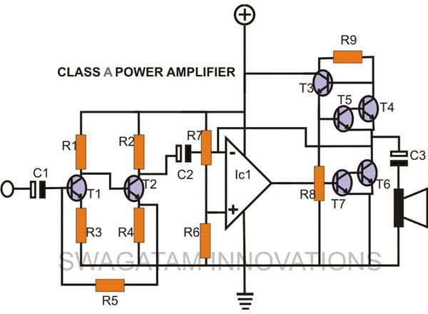
A straightforward circuit schematic of a class A test amplifier provided here, can be easily built by you. The required parts may be procured and neatly assembled over an appropriately sized general PCB. Remember to mount the output transistors over large heat sinks.
The entire assembly along with the power supply may be housed inside a suitable metallic enclosure allowing only the mains cord out of the box. The body of the enclosure should be grounded to the negative of the power supply.
Keep appropriate outlets terminals for the speaker connections so that the wires of the speaker units can be connected to these points.
Parts List
You will need the following parts for the project:
All resistors are 1/4 watt, CFR, 5%, unless otherwise specified.
R1 = 22K
R24K7
R3 = 180E
R4 = 820E
R5 = 100K
R6,7 = 10K
R8 = 5K6
R9 = 0.5 E 2W
C1,2 = 4.7uF/25v
C3 = 2200/ 50V
T1,2,3 = BC547
T4,5,6,7 = 2N3055
IC1 = 741
VOLTS = 24 V /2A
Circuit Description
Let’s now study how the circuit functions from the following points:
Transistor T1 and T2 along with the other associated components is wired into a high quality low signal amplifier. The quality of this stage is enhanced due to the applied AC and DC feedback voltages from the emitter of T2 to the base of T1.
IC 741 is wired as an inverting AC amplifier and increases the received input to a level sufficient to the output stage.
The output stage is primarily comprised of power transistors T6 and T7, configured as high power emitter follower Darlington pair.
The impedance of this stage is very high, in the range of several mega ohms with a bandwidth extending well above 100 Khz.
The other power transistors T3, T4 and T5 are rigged into a constant current source and provide the necessary quiescent current to the output stage.
This constant current circuit is particularly responsible for setting the output free of the unwanted line variations and ripples.
Specification Summary
A brief specification summary of this diy class A amplifier is provided as under:
-
Bandwidth: 15 Hz to 35 Khz.
-
Total Harmonic Distortion: < 0.1% just before clipping,
-
Input Impedance: 2 M Ohms
-
Sensitivity: 180 mV at full output.