Adjustable 1 to 25 Volt DC Power Supplies - Circuit Schematic Diagram and Plans
Introduction
An electronic work bench without an adjustable DC power supply is incomplete. And in most cases the purpose of a power supply is rendered useless if its capabilities are limited. Generally when we talk about power supplies, they are either fixed voltage type or at the most a continuously variable type. They prove to be quite inadequate when it comes to testing of sophisticated electronic circuits.Ideally a DC universal power supply can be very handy, but only if it accommodates the following features:
- 1-25V DC continuously variable,
- 0-2Amps. Continuously variable,
- short circuit and overload protected,
- Hum free, stabilized output.
The circuit of a universal power supply described here, complete with schematic diagram and parts list, fulfills all the above criteria and more importantly, the construction costs hardly anything.
Parts List
The parts required for the construction of the universal power supply are:
- R1- 0.33 Ohms, 5 watt Wire Wound,
- R2, R4- 680Ohms, ¼ watt,
- R5- 470Ohms, ½ watt,
- R6- 150Ohms, ½ watt.
- R3, R7- 2k7, ¼ watt,
- T1- TIP 33,
- T2, T3- BC547B,
- VR1, VR2- 4k7 linear pot.
- C1- 1000uF/ 25V, elect. Cap.
- D1- 1n4007,
- General purpose board- 2” x 4”
- Metallic box as per size,
- Transformer- 0- 25V, 3 Amps.
- Mains cord, screw nuts, lugs etc.
Circuit Description
The present circuit of the universal DC power supply functions in the following manner:
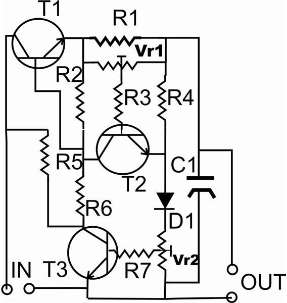
- When power is applied at the input of the circuit, resistor R initiates the power transistor T1,
- It switches ON and the power reaches the output via the current sensing resistor R1,
- The feedback components comprising D1, VR2 and T3 restricts the output to a voltage set by VR2,
- The capacitor at the output of the universal power supply filters out any residual pick-up to end up into a clean stabilized output voltage,
- During a short circuit or an overload at the output, the potential developed across R1 switches on T3, which neutralizes the base of T1 so that the output voltage drops and the short is checked. Adjusting VR1 can set the maximum current limit.
Construction Tips and Schematic Diagram
The construction of this universal DC power supply is quite simple and is completed with the help of the given schematic diagram. The following points should be taken care of:
- During overloads transistor T1 may get quite heated up. For its proper functioning in such conditions, sufficient cooling may be required and therefore be fitted a TO-220 type of heat sink.
- Current sensing resistor R1 should be a wire wound type, so that it does not get burnt during a short circuit.
- Optionally a voltmeter and an ammeter may be incorporated to monitor the changes in the load conditions.
- The completed circuit board of the universal power supply should be tightly secured to the base of the metallic enclosure,
- The earth or the negative wire should be connected to the metallic box with the help of lug, screw and nut. This will help in reducing hum.
- Make sure that the heat sink of T1 does not touch the metallic enclosure, which may result in a short circuit.