Digital Logic Design: IC Families Explained
Introduction
In Digital Electronics, a logic family refers to digital integrated circuit devices which are constructed witha combination of electronic gates. A family has its own power supply voltage and distinct logic levels. Some families were also introduced as individual components which were used to design integrated circuits and also to interconnect them. Each family has its own characteristics, advantages and disadvantages. Also within each family, there is a range of voltages which may be high level or low level. These families are listed below:
- Diode Logic (DL)
- Resistor-Transistor Logic (RTL)
- Diode-Transistor Logic (DTL)
- Transistor-Transistor Logic (TTL)
- Emitter Coupled Logic (ECL)
- Complementary Metal Oxide Semiconductor Logic (CMOS)
Let’s look at each family’s design according to their characteristics, advantages, disadvantages, and use.
Description and Characteristics
Diode Logic (DL)
In Diode logic, all the logic is implemented with the use of resistors and diodes. It is essential that the diode is forward biased so that it can conduct. In diode logic, the purpose of the diodes is to perform OR and AND operations. Diodes can also be used as a logical switch. The disadvantage of Diodes is that they tend to degrade the signals quickly. Diodes also cannot work for multiple stages, only one stage at a time. The diodes also cannot perform the NOT operation which limits their functionality.
Resistor-Transistor Logic (RTL)
In resistor-transistor logic, all the logic is implemented with the use of transistors and resistors. In this logic, input signals are combined with the use of transistors. These input signals are then inverted and amplified. Sometimes an extra transistor is needed to re-amplify the signal. Resistor-Transistor gates are not very expensive and are very simple to construct. The drawback in using RTL gates is that they draw a great amount of current from the power supply. They are used in slower applications, but cannot be used in today’s computers as they cannot switch at high speeds. RTL gates can be used as amplifiers as well to amplify small signals. They can also be used as an interface between digital and linear circuits.
Diode Transistor Logic (DTL)
In Diode-transistor logic, all the logic is implemented with the use of diodes and transistors. DTL has some advantages over DL and RTL. As the diodes can perform AND and OR operations but along with a transistor the output signal can be amplified. In DTL, the signal can be restored to full logic levels if we add a transistor at the output of the logic gates. This results in logic inversion. Another advantage of DTL is that the OR operation can be performed by the diodes instead of resistors. This removes the interaction between input signals. But the switching speed of the transistor is limited due to the input resistor to transistor. DTL was used in early vacuum tube computers.
Transistor-Transistor Logic (TTL)
In transistor-transistor logic, the logic gates are constructed around the transistors. It was first introduced in 1964. TTL uses bipolar transistors to construct its integrated circuits. There have been different versions of TTL:
- Standard TTL.
- High speed TTL.
- Low power TTL.
- Schhottky TTL.
We will only discuss the basic TTL. All the TTL families above have three configurations namely:
- Totem-Pole output.
- Open collector output.
- Tristate output.
The input sections of TTL consists of a phase splitter transistor and an input transistor.The input transistor conducts when the emitter-base junction becomes forward biased.
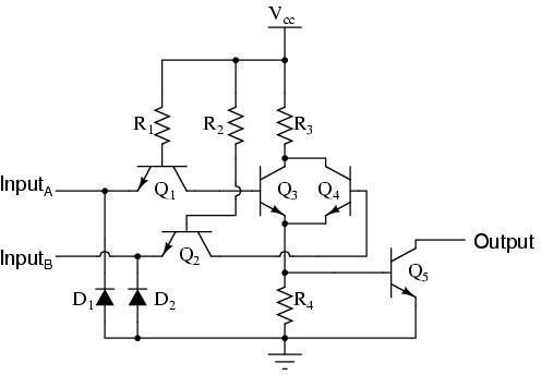
TTL has become the standard logic circuit in many application for a number of years. TTL greatly decreases the manufacturing costs because multiple emitters can be added in the input so no extra space is needed and a multiple input gate can be constructed easily. The output circuit has also been modified in recent years and the the configuration is called “Totem pole”. A commercial IC package of TTL includes three three-input gates, four two-input gates, or two four-input gates. The structure of the IC always remains the same.
Emitter Coupled Logic (ECL)
In Emitter coupled logic, the transistors are prevented from going into deep saturation so that there are no storage delays. This logic is used in applications with high speed environment. ECL is considered to be one of the best because there is a very low propagation delay. In fact, it is the fastest bi-polar circuit available today. ECL was first introduced in 1962. This logic family bypasses TTL in terms of speed. ECL is also a non-saturated logic. The logic levels for ECL are normally -0.9V for high logic and -1.6 for low logic. The design of ECL consists of termination resistors which allows the signals to propagate with very low reflection.
Complementary Metal Oxcide Semiconductor Logic (CMOS)
CMOS is known for its low power consumption and high fan-out. The transistors inside the CMOS are made from an NMOS transistor and PMOS transistor. To realize the logical functions, both P-type and N-type transistors are used. It is currently being used in microprocessor technology and Application Specific Integrated Circuits. There is no power dissipation in CMOS. It is also considered to be one of the most reliable logic family today.
