How to Build a Smart Automotive Circuit Breaker? A Permanent Solution To All Car Electrical Hazards
Introduction
In one of my articles I have discussed regarding the drawbacks of ordinary car fuses generally used in most of the cars and how inefficient they can be in case of a short circuit.
Here we will know regarding the construction of a ‘smart’ electronic automotive circuit breaker which will put to an end to all possible car electrical hazards and provide a permanent solution for the same.
Parts List
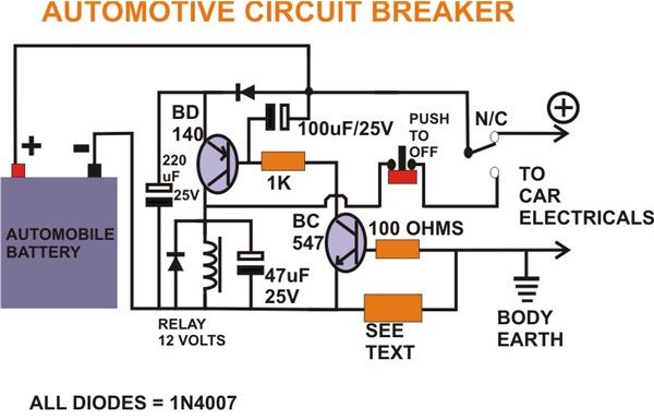
You will require the following parts for the construction of the electronic car fuse:
- Transistors BC547, BD140 - 1 each,
- Resistors 100Ω, 1K - 1 each( 1/4 watt ),
- Resistor 0.1Ω - 1 no.( see text ),
- Diode 1n4007 - 2 nos.
- Capacitors 220uf/25V, 100uf/25V, 47uF/25V - 1 each.
Assembly
The construction of the electronic car fuse circuit is carried out in the following simple steps:
- First construct the 0.1 Ohms current sensing resistor.
- A 5 inch long, 18 SWG iron Wire will do the job nicely. Since this resistor may not fit on the board, keep it aside.
- Finish the board assembly using the transistors, resistors, diodes, capacitors etc. as per the diagram.
- Now connect the current sensing resistor and the relay to the appropriate parts on the board using flexible wires.
- Also, connect the input and the output wires (make sure they can handle at least 50 Amps. of current) to the assembled circuit board.
- Finally select a suitable, sturdy ABS cabinet, fit the board, clamp the relay and the current sensing resistor.
- Drill proper holes on the cabinet to let the wires out of the box.
Testing
The Testing of the electronic car fuse circuit can be done in the following method:
- Connect the input supply wires to a 12 Volt automobile battery, and the output wires to a 100 Watt halogen lamp.
- Since it is not a short circuit or an over load, the lamp should glow, the relay should not trip.
- Try connecting another 100 Watt halogen lamp in parallel to the existing lamp,
- Now the relay should immediately trip and latch, disconnecting the power to the lamps.
- Making a short circuit at the out puts should also give the same result.
- Tripping point( maximum current ) may be altered by decreasing the length of the current sensing resistor and vice cersa, but it should be within the maximum limit of the current handling capacity of the relay contacts.
- Once the relay is latched, it can be restored by pressing the given ‘push to off’ switch (First make sure that the short circuit or the over load has been corrected).
Brief Circuit Description
The Functioning of the circuit of the electronic automotive circuit breaker can be better understood through the following simple steps:
- When an over load or a short circuit occurs, huge current flows through the current sensing resistor.
- Due to this a potential difference develops across the current sensing resistor.
- This voltage triggers the transistor BC547.
- This transistor in turn amplifies enough current to the base of transistor BD140, so that it can energize the relay.
- The relay contacts change position and self latches itself through its N/O contacts and breaks the circuit.
- At the instant the relay changes state, there is a brief failure of power to the circuit. The capacitor at the base of BD140 and the diode 1n4007 ensures that the circuit operates smoothly even during that instant.
The reset switch may be fixed somewhere within the reach of the driver.