JK Flip Flop Circuit using RS flip flop
Introduction
In the previous article we discussed about the realization of D flip-flop using SR flip-flop. In this article let’s discuss about the conversion of RS flip-flop into JK flip-flops. We know that Jk flip-flops are one of the important and most widely used flip-flops. So often there is a need for conversion of other type of flip-flops into JK flip-flops. Let us discuss about this conervsion in detail.
The Transformation
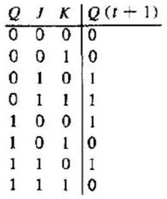
Before dealing with the conversion let’s summarize the truth table of JK flip flop circuits.
From the truth table it’s quite evident that 4 main transitions occur between the current state and next state of JK flip-flop.
They are 0->0; 0->1; 1->0; 1->1.
0-> 0 Transition:
For both the present state and the next state to remain in 0, the J input must remain at 0 and the K input can either be 1 or 0. In simple words, irrespective of the value of K input, the present state and next state remains in 0, if the value of J input is 0.
0->1 Transition:
This is the transition where the present state is 0, but the next state should change to 1. For this transition to occur the value of J input should be 1 and K input can either be 0 or 1. When K value is 0, it is called SET condition (J=1 and K=0, SET condition) and when K value is 1, it is called toggle condition. (J=1 and K=1, TOGGLE condition). So for this transition to occur J has to be high, but K can be either high or low.
1-> 0 Transition:
In this case the present state is 1 and the next state should be 0. For this transition to occur the value of K input should be 1 and the value of J input can be either 0 or 1. Irrespective of the J input, the transition occurs if the value of K remains at 1.
1->1 Transition:
For this transition to occur the value of K should remain low or 0, irrespective of the value of J. J can be either 1 or 0. The value of J will not affect this transition.
From the above transitions we can form the excitation table as shown below.
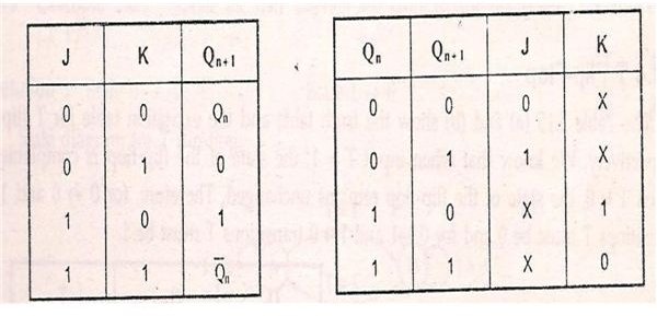
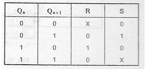
The four transitions and excitation table of RS flip-flop is shown below.
Steps to Convert RS flip-flop to JK Flip-flop
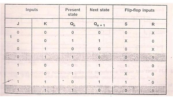
- Form the excitation table using S, R, J, K, Q (n) and Q (n+1).
- When J and K inputs are 0 and Q (n) is 0, Then the next state Q (n+1) is also 0. The R an S inputs corresponding to this transition are X and 0 respectively. X is nothing but don’t care condition. In simple words the value of R will not affect the next state of the system. Irrespective of the value of R input, the present state and the next state remains in 0, if the value of S input is 0. Similarly when the inputs J and K are 0 and the present state Q (n) is 1, then the value of the present state is retained for next state too. This is nothing but the 1->1 transition. The S and R input values corresponding to this transition is S=X and R=0. That is S input can be either 0 or 1.
- Consider when J input is 0 and K input is 1. During this condition, the present state is 0 and the same is retained for the next state also. So both the present and next state is 0 and there is a 0-> 0 transition. The value of R and S inputs corresponding to this 0->0 transition is S=0 and R=X. The value of R input does not affect the state of the system. So it is denoted as X. Similarly when J=0 and K=1 and the present state Q (n) is 1, then the next state switches to 0. So in this condition a 1->0 transition occurs. Now the value of RS inputs can be derived from RS excitation table. From the excitation table the value of R and S inputs corresponding to this transition is S=0 and R=1.
- Similarly the entire excitation table for conversion of RS to JK flip-flop can be derived. The excitation table is as shown.
- Draw the K-map for R and S inputs separately using J and K Q (n). Where J and K are inputs of JK flip-flop and Q (n) is the present state of the flip-flop
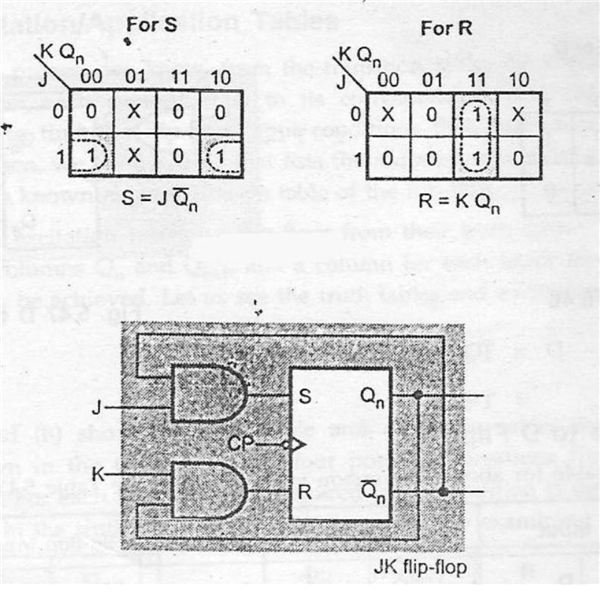
- From the K-map we can form a relation between SR and JK flip-flops. A characteristic equation can be obtained which expresses R and S in-terms of J and K. Using this characteristic equation, a logic diagram can be formed which is nothing but the pictorial representation of SR to JK conversion.
- From the K-map the characteristic equation is S=J. Q’ (n) and R=K. Q (n). The Characteristic equation is pictorially represented as logic diagram.
In the next article let us discuss about the other types of realizations.