Microprocessors engineering - Interfacing the 8085 microprocessor
Introduction
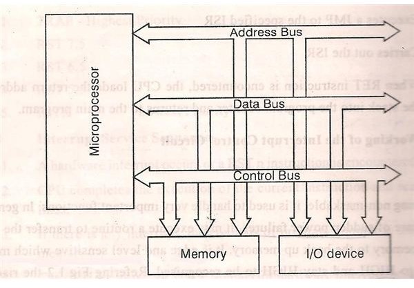
We know that a microprocessor is the CPU of a computer. A microprocessor can perform some operation on a data and give the output. But to perform the operation we need an input to enter the data and an output to display the results of the operation. So we are using a keyboard and monitor as Input and output along with the processor. Microprocessors engineering involves a lot of other concepts and we also interface memory elements like ROM, EPROM to access the memory.
Interfacing Types
There are two types of interfacing in context of the 8085 processor.
Memory Interfacing.
I/O Interfacing.
Memory Interfacing:
While executing an instruction, there is a necessity for the microprocessor to access memory frequently for reading various instruction codes and data stored in the memory. The interfacing circuit aids in accessing the memory.
Memory requires some signals to read from and write to registers. Similarly the microprocessor transmits some signals for reading or writing a data.
But what is the purpose of interfacing circuit here?
The interfacing process involves matching the memory requirements with the microprocessor signals. The interfacing circuit therefore should be designed in such a way that it matches the memory signal requirements with the signals of the microprocessor. For example for carrying out a READ process, the microprocessor should initiate a read signal which the memory requires to read a data. In simple words, the primary function of a memory interfacing circuit is to aid the microprocessor in reading and writing a data to the given register of a memory chip.
I/O Interfacing:
We know that keyboard and Displays are used as communication channel with outside world. So it is necessary that we interface keyboard and displays with the microprocessor. This is called I/O interfacing. In this type of interfacing we use latches and buffers for interfacing the keyboards and displays with the microprocessor.
But the main disadvantage with this interfacing is that the microprocessor can perform only one function. It functions as an input device if it is connected to buffer and as an output device if it is connected to latch. Thus the capability is very limited in this type of interfacing.
Programmable Peripheral Devices
Programmable peripheral devices were introduced by Intel to increase the overall performance of the system. These devices along with I/O functions, they perform various other functions such as time delays, counters and interrupt handling. These devices are nothing but a combination of many devices on a single chip. A programmable device can be set up to perform specific function by writing a code in the internal register. As this code controls the function of the device it’s called control word and internal register in which it is stored is called Control Register.
INTEL developed some peripheral devices for processors like 8085/8086/8088. The peripheral devices includes
8255 – Parallel Communication Interface (PPI)
8251 – Serial communication Interface (USART- Universal Synchronous/Asynchronous Receiver/Transmitter)
8257 – DMA Controller
8279 – Keyboard/Display Controller
8259 – Programmable Interrupt controller
8254 – Programmable Timer
Types of Communication Interface
There are two ways in which a microprocessor can connect with outside world or other memory systems.
Serial Communication Interface
Parallel Communication interface
Serial Communication Interface:
In serial communication interface, the interface gets a single byte of data from the microprocessor and sends it bit by bit to other system serially (or) the interface receives data bit by bit serially from the external systems and converts the data into a single byte and transfers it to the microprocessor.
Parallel Communication Interface:
This interface gets a byte of data from microprocessor and sends it bit by bit to the other systems in simultaneous (or) parallel fashion. The interface also receives data bit by bit simultaneously from the external system and converts the data into a single byte and transfers it to microprocessor.
Consider that we have a microprocessor interfaced to both I/O device and also a memory chip. Now how to select between the two devices according to the requirement?
For this purpose an address decoding circuit is used. An address decoding circuit aids in selecting the required I/O device or a memory chip.
Let us discuss the concept of Memory interfacing and I/O interfacing in the next article.