JK Flip Flop Diagram & Truth Tables Explained
JK Flip-Flop
In the previous article we discussed RS and D flip-flops. Now we’ll lrean about the other two types of flip-flops, starting with JK flip flop and its diagram.
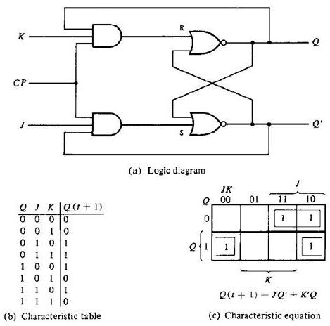
A JK flip-flop has two inputs similar to that of RS flip-flop. We can say JK flip-flop is a refinement of RS flip-flop. JK means Jack Kilby, a Texas instrument engineer who invented IC. The two inputs of JK Flip-flop is J (set) and K (reset). A JK flip-flop is nothing but a RS flip-flop along with two AND gates which are augmented to it.
The flip-flop is constructed in such a way that the output Q is ANDed with K and CP. This arrangement is made so that the flip-flop is cleared during a clock pulse only if Q was previously 1. Similarly Q’ is ANDed with J and CP, so that the flip-flop is cleared during a clock pulse only if Q’ was previously 1.
When J=K=0
When both J and K are 0, the clock pulse has no effect on the output and the output of the flip-flop is the same as its previous value. This is because when both the J and K are 0, the output of their respective AND gate becomes 0.
When J=0, K=1
When J=0, the output of the AND gate corresponding to J becomes 0 (i.e.) S=0 and R=1. Therefore Q’ becomes 0. This condition will reset the flip-flop. This represents the RESET state of Flip-flop.
When J=1, K=0
In this case, the AND gate corresponding to K becomes 0(i.e.) S=1 and R=0. Therefore Q becomes 0. This condition will set the Flip-flop. This represents the SET state of Flip-flop.
When J=K=1
Consider the condition of CP=1 and J=K=1. This will cause the output to complement again and again. This complement operation continues until the Clock pulse goes back to 0. Since this condition is undesirable, we have to find a way to eliminate this condition. This undesirable behavior can be eliminated by Edge triggering of JK flip-flop or by using master slave JK Flip-flops.
The characteristic table explains the various inputs and the states of JK flip-flop.
T Flip-Flop
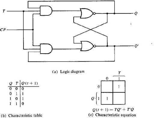
T flip-flops are similar to JK flip-flops. T flip-flops are single input version of JK flip-flops. This modified form of JK flip-flop is obtained by connecting both inputs J and K together. This flip-flop has only one input along with Clock pulse. These flip-flops are called T flip-flops because of their ability to complement its state (i.e.) Toggle. So they are called as Toggle flip-flop.
When T=1 and CP=1, the flip-flop complements its output, regardless of the present state of the Flip-flop. In this case the next state is the complement of the present state.
When T=0, there is no change in the state of the flip-flop (i.e.) the next state is same as the present state of the flip-flop. From the characteristic table and characteristic equation it is quite evident that when T=0, the next sate is same as the present state.
Applications Of Flip-Flops
• Counters
• Frequency Dividers
• Shift Registers
• Storage Registers
These are the various types of Flip-flops which are being used in Digital electronic circuits and the applications of Flip-flops are as specified above.
Image and Content Courtesy:
“DIGITAL LOGIC DESIGN” by Morris Mano