Construction and Principle of Operation of the Shunt DC Motor
The construction of a DC Shunt Motor is the same as any other DC motor. It contains all the fundamental parts, which include a stator (field windings), a rotor (also known as armature), and a commutator.
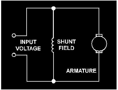
Stator/Shunt Windings
Input power is supplied to the stationary element of the motor, i.e. the shunt winding. The shunt field winding is made of several turns on the coil of fine gauge wire. As the turns are made up of thin wire, the shunt winding is quite small in size. Unlike heavier gauges of wire in the winding in series motors, the shunt winding in this motor cannot carry very high current.
Rotor/Armature
The armature, generally called the “rotor,” handles the shaft load. It has a heavier gauge wire so it can support higher current. High current passes through the armature during the motor start up or when the motor is running at lower speed. As the motor’s speed increases, the armature generates counter-electromagnetic force opposing the current in the armature.
Commutator
The commutator and brush arrangement provide current from the static field windings to the rotor. Torque in the machine is generated by the interaction of the magnetic field of the windings and armature.
Principle of Operation
When electric voltage is supplied to the shunt DC motor, due to high resistance of the shunt winding, it draws very low current. The higher number of turns of the shunt winding helps in generating a strong magnetic field. The armature draws high current, thus also generating a high magnetic field. The motor starts rotating as the magnetic field of the armature and shunt winding interact. As the magnetic fields grow stronger, rotational torque will increase, thus resulting in an increase of rotational speed of the motor.
A shunt DC motor has a feedback mechanism that controls its speed. As the armature rotates in a magnetic field, it induces electricity. This EMF is generated in a reverse direction, thus limiting the armature current. So the current through the armature is decreased and speed of the motor is self-regulated. The shunt winding cannot bear high current at starting like a series motor because of its fine wire build, so shunt motors are used to handle small shaft loads that only need low torque initially.
Motor Speed
Speed is totally dependent on shaft load in series motors. In series motors, the load is inversely proportional to the speed of armature. If the load is high, the armature will rotate at a low speed. If the load is less, armature speed will increase. The speed of the armature is infinity or uncontrolled with no load.
Unlike series motors, the speed of the shunt motor is independent of the shaft load. As the load to the motor increases, the speed of the motor slows down instantaneously. Slowing down the speed reduces the back EMF, which in turn increases the current in armature branch. This results in the increase of the motor speed. On the other hand, if load is decreased, then motor speed will rise instantaneously. This in turn will increase the counter EMF, thus reducing current to the motor. Gradually the motor will reduce it’s speed. As a result, the DC shunt motor is capable of maintaining a constant speed irrespective of load changes. Because of this feature, this motor is used for automotive and industrial purposes where fine precision of the motor speed is required.
Motor Speed Control
One can control the speed of a DC shunt motor in two ways:
- By varying the current supplied to the rotor
- By varying the current supplied to the stator
As the voltage around the rotor and stator is the same, the speed of the motor can be controlled by controlling the current through the stator or rotor. The current through the stator and rotor branches can be controlled by varying their resistance or by using a silicon controlled rectifier (SCR). The resistance can be increased in the shunt winding and armature branch by placing a rheostat in series. As the armature handles much higher current than the field winding, so the rheostat for controlling current in the armature branch is quite large. This is why having the current controlling rheostat in the field winding is generally preferred.
Shunt field current can change the speed of the motor by 10-20%. As the current through the shunt winding increases, the speed of the rotor increases, thus yielding higher back EMF to maintain the equivalent decrease in current of armature. Conversely, by decreasing the current through the shunt winding, the speed of the motor can be decreased.
Speed of the shunt DC motor also decreases when the motor is operated at lower voltage than its rated voltage, but this makes it inefficient with a tendency to become overburdened and overheat. Generally, motors come with a specified rated speed in RPM and rated voltage. When a shunt DC motor functions below its full voltage, its torque is reduced. For these reasons, it is recommended not to operate the motor below its specified voltage rating.
References
- The DC Shunt Motor, http://www.industrial-electronics.com/elecy4_1.html
- DC Machines and DC Motors, http://www.educypedia.be/electronics/motordc.htm
- DC Motor, http://www.electricmotors.machinedesign.com/guiEdits/Content/bdeee3/bdeee3_1-1.aspx
- Image By Awn Muhammad