How to Make a Simple Radio Using the IC ZN 415
About the IC ZN 415
In the late eighties “Ferranti” introduced this wonderful little chip (IC ZN414) which could receive and process AM radio signals all by itself without involving complex component and tuning networks normally associated with discrete radio circuits. Using this IC it became possible to manufacture very small match box-sized radio sets, which within no time became very popular among school kids and the electronic enthusiasts. Some years later the company further introduced an improved version of this IC in the form of the ZN 415.
Although to many, ICs are just “black boxes,” it may be rather interesting to know what really goes on inside, especially when something is so tiny, yet equipped with such outstanding features:
A ZN415 actually consists of an embedded ZN414 inside its package.
The IC ZN414 is basically a ten stage radio tuner and is capable of performing the specified function of receiving and tuning the radio signals only. For amplifying these signals into the headphones, an external amplifier section needs to be employed for enabling the signals to be heard.
In the modified IC ZN415 version, the need for the above external amplifier stage is eliminated by incorporating a built-in two-transistor amplifier stage within the package. This feature enables direct connection of the headphones to the relevant IC pin outs for listening to the received radio signals. Thus making a radio with this IC becomes amazingly simple.
A more elaborate technical discussion is given below:
The frequency range of reception covered by this chip is from 150 kHz to 3 MHz. The range is pretty wide and clearly includes even the long wave bands along with all the MW broadcast bands.
The audio frequency output is around 1 and 1.5 milliwatts into a pair of 64 Ω headphones.
Selectivity is good: 8 kHz bandwidth at -6dB due to the high input sensitivity of the IC, which is typically around 4 MΩ.
An increase of less than 7 dB can be witnessed in the AF output for more than 30 dB RF input, as per the AGC characteristics of the IC.
Image Credit: google.co.in
A Practical ZN415 Radio Circuit
The figure shows a full-fledged MW/LW radio receiver circuit using the IC ZN415. The circuit of this simple radio can be easily built over a general purpose PCB by interconnecting the components as shown in the diagram by soldering.
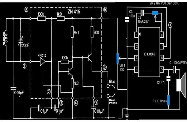
The circuit includes an AF amplifier using the IC LM386 which is able to drive an 8 Ohm loudspeaker and deliver a good 1.25 watts of music power; the volume can be adjusted through VR1 to the desired levels.
The addition of the above amplifier stage makes it necessary to increase the supply volts up to 9 for proper functioning of the amplifier stage; the ZN 415 is able to operate at voltages as low as 1.5, though.
It would be interesting to note that in the above design, listening through headphones still becomes possible via pin #5 of the IC.
The external tuning agent includes a tank circuit made up of an antenna coil and a matched variable capacitor or the GANG.
The antenna coil may be procured ready-made or simply constructed at home with the following steps:
For receiving MW signals the aerial coil can be made by winding 55 turns of a single layer of 0.22 mm super enameled copper wire over a 60 × 12 × 3 mm ferrite rod.
For both MW and LW receptions the above winding is reduced to 48 turns for the MW section and an additional 280 turns multilayered coil is wound over one of the ends of the MW coil. Here the rod dimensions become 150 × 12 × 3 mm.
With both the functions incorporated, the addition of a 10 pF capacitor becomes necessary across the LW winding for clean reception and, of course, also a band selector switch.
References
Literature: Ferranti Semiconductors - Advance Product Information: ZN 415E an AM Radio Receiver.