How to Control the Speed of a DC Motor Using IC L165
DC motors which employ permanent magnets operate as independently energized motors. Ideally, the speed of DC motors having very low internal resistance is directly proportional to the voltage applied and is not related to their torque. The speed control described here actually happens due to the voltage drops across the internal resistance Ri of the motor.
Thus we find that when such a motor is loaded, the current consumption rises resulting in an increased voltage drop across its winding which ultimately affects and drops the supply voltage significantly.
So how do we control the speed of a DC motor efficiently? The drawback can be avoided by employing an Ri compensation, a system where the instantaneous current consumptions of the loaded motor is measured and the resultant “voltage drops” are corrected by raising the supply voltage to the required levels.
The above theory is well accomplished using the IC L165 by SGS Thomson.
Circuit Description
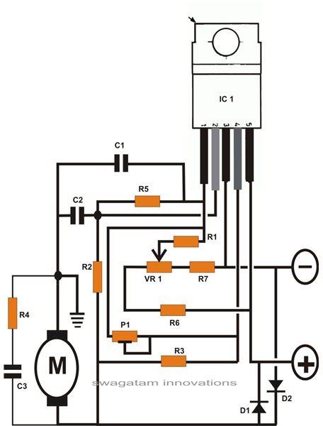
The figure on the left shows one practical design using the IC L165 which is a power op amp designed for handling output powers up to 3 amps at a maximum voltage of 36 V, and which eminently suits the proposed application.
The circuit is reasonably balanced and further modifications are not recommended, which may possibly and easily induce a lot of instability in the design.
The following points explain the terms associated with the circuit:
Noise interference is checked by introducing the capacitors C1, C2, C3, and R4; however a few of these may be omitted for specific loads, which will discussed in the later part of the article.
Diodes D1 and D2 protect the IC from voltages arising due to commutations.
After connecting an appropriate load (DC motor), the power is switched ON. The Ri compensator preset P1 is adjusted for stabilizing the rotations of the connected motor to a uniform level. However, over-optimization may produce apparently uncontrollable movements.
Preferably P1 is adjusted immediately after the motor starts and before its armature warms up to its normal temperatures and results in an increase in its internal resistance.
The circuit uses a dual symmetrical supply which facilitates two quadrant operation of the connected motor. The feature becomes ideally suitable for controlling model trains where two way operations become typically desirable. Thus here the motor is made stationary by keeping the slider arm of the pot VR1 exactly at the center and then using incrementing or decrementing motions by shifting it to the relevant directions, i.e. towards the positive or the negative sides.
The circuit also becomes very favorable for operating and controlling small portable DC drill machines like PCB drilling machines. Here the use of 24 and higher volts becomes necessary and therefore the application becomes perfectly compatible with the present design.
Precautions
A motor being a complex device with varying torques and back EMFs, the rotor introduces a considerable capacitance. Also noise suppressing components tend to increase the complexity, resulting in instability of the motor movement (occasional stuttering). Therefore some careful optimization techniques become essential for deriving optimum response from the circuit.
Experimenting with R4, C3 (by eliminating them initially) can prove useful for drill machines where the inclusion of C2 becomes quite handy. With loads having built-in noise suppressors, C2 may be excluded and R5 added for protecting the op amp against sudden differential voltage peaks.
The IC being subjected to high currents may heat up considerably and therefore should be mounted over a suitably large heatsink.
If the above design does not fulfill your requirements, you may refer to another similar circuit here, which may further help you to understand how to control a DC motor speed.
Parts List
Resistors are all 1/4W, 5% CFR unless stated.
R1 = 100K,
R2 = 10K,
R3 = 0.56E/5W,
R4 = 10E,
R5 = 1K,
R6, R7 = 560E,
C1 = 104 PPC,
C2 = 103 PPC,
VR1 = 4K7, LINEAR,
P1 = 22K, LINEAR
D1, D2 = 1N4007,
References
ST Microelectronics - L165 Datasheet
Book - Elektor electronics (India)