How to Make a Motion Detector Alarm Circuit
A motion detector equipment will do exactly the way it’s named – detect a motion or a movement within the range of its set sensitivity and subsequently raise an alarm. Needless to say these are used for securing restricted zones or simply for monitoring unwanted occupations. Compared to other types of popular security devices and concepts, a motion detector alarm is comparatively more reasonable and accurate. That’s simply because the operating principle of these devices make them detect only genuine intrusions and only around the restricted area, so whenever an alarm is sounded through it, you can be certain that an infiltration has taken place.
In this article we will study a simple to build yet accurate circuit of the above discussed device. Many of these circuits which depend and operate as soon as obstruction is created by an intruder in the path of an artificially generated light, can probably be considered a little inefficient. Because the positioning of an external light source involves criticality and requires complete darkness to become operative, unless it’s a costly infra red system, however even that doesn’t relieve the system from depending on an external compatibility.
The circuit presented here is exclusively developed by me. The idea involves pretty straightforward concept of detecting light differences over a couple of sensors instead of a single one. Importantly, the use of two sensors makes it functional with any type of sample light source available, for example daylight entering the premise from the windows or the street light that may be accessible during nights.
Let’s figure out the circuit functioning with the following section.
Motion Detection Devices
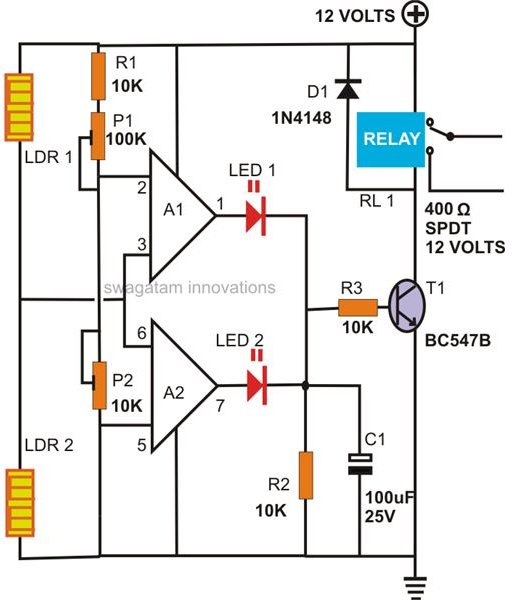
The diagram alongside depicts a rather simple configuration of a window comparator circuit involving just a couple of op amps, LDRs and very few other passive components.
As the above name suggests the circuit will remain in the passive state as long as the light levels over the LDRs are relatively equal or within the set “window” area.
Use of two LDRs or sensors makes it possible for the circuit to function with any available light intensity, as here the intensity is immaterial and it’s rather the difference in the light levels incident over the LDRs which may be required to toggle the output.
In the passive mode, i.e. as long as the light levels are equal over the LDRs, the output of the opamps remains at logic zero.
Now as soon as a difference in light level (which can happen if somebody steps in between the light source and any one of the LDRs) is “felt,” the relevant opamp output will immediately go high triggering the output relay driver stage and the subsequent alarm.
This concludes the circuit operation part as there’s hardly anything to be explained.
The setting up procedure though needs a bit of attention, and may be done with the following points:
After assembling the circuit carefully as per the schematic, position the circuit firmly at a particular point such that it faces an incoming light source (from your house lights or simply the daylight.)
Since the above light is situated at a relatively far away distance, you can be sure that it produces almost equal amount of levels over both the LDRs.
In the unadjusted position the motion detector alarm circuit will operate and keep the output switched ON, so now you may want to adjust the presets so that the output just deactivates.
To confirm the functioning, try walking or moving your palm quickly in between the light source and the circuit, you will be amazed by its instant response when the output of the circuit latches and immediately raises the alarm.
The entire circuit may be enclosed inside an ABS enclosure with a built-in alarm section.
The LDRs might be required to be held at least a foot apart from each other, so that means that they may need protrude out of the housing appropriately.
References
-
Author’s own experience.
Image - Drawn by the author.