Carbon Pile Regulators - How They Work
Carbon Pile Regulators
An excitation system of an A.C. generator consists of a direct current generator and a voltage controlling unit known as the voltage regulator. An excitation system’s main function is to supply and control the direct current for the rotor pole windings. Voltage regulators are of several types and are used depending on the generator requirement. The level of excitation current and the resulting field pole strength produced is adjusted automatically using an AVR (automatic voltage regulator) attached to the system.
The early alternators were provided with an excitation system that consisted of a small D.C. generator, and the voltage was regulated mainly by a carbon pile regulator. In this article we will learn about the construction and operation of a carbon pile regulator.
An Alternator with a Carbon Pile Regulator
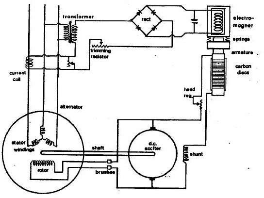
As shown in the diagram, the alternator has a direct current exciter whose armature is mounted on the extension of an alternator shaft. The D.C. exciter is a small shunt generator wherein the majority of the current of the armature is supplied to the alternator rotor windings through a slip ring and carbon brush arrangement. The trimming resistor and hand regulator shown in the sketch is for the adjustment of initial setting of the main regulator.
Operation of the Circuit
The current generated from the regulator arrangement produces a magnetic field. When rotating, the rotor causes a magnetic flux to be produced, and this flux is cut by the stator windings. This results in the generation of a voltage and current output in the stator windings.
A small part of the current produced in the stator windings is passed to the shunt field so as to provide excitation for the DC exciter itself. The amount of current flow through the exciter shunt field is controlled by a resistance, which is made up of carbon discs or a carbon pile packed into a ceramic tube.
The resistance of the carbon disc is varied by pressure change. This pressure is controlled by a magnetic field produced by an electromagnet coil. The current for this electromagnetic coil is supplied through the transformer and rectifier circuit from alternator output to the terminal board. This means that as the load changes the alternator voltage also varies. The strength of the electromagnet also increases or decreases due to this load change, resulting in the change in the compression on springs and thus the resistance of the carbon pile.
The resistance of the carbon is least when the pressure on springs is least and on the armature greatest. This occurs only when there is low output voltage which causes solenoid to be weak. Due to this effect, low resistance and more current flows to the shunt and high excitation is produced. This high excitation when fed to rotor produces more voltage.
In the same manner, the pressure will be low when strong solenoid field is present in the arrangement, i.e. when alternator voltage is high. Due to this a small amount of current is conveyed to the shunt, mainly because of high resistance, resulting in less excitation and reduced output voltage.
References and Image Credits
Marine electrical Equipment and Practice by H.D Mc George