Exploring Multiplexers-Demultiplexers
The demultiplexer is the inverse of a multiplexer in that it takes one input and delivers more than one output. Simply put, the demux receives a single signal and distributes it among multiple channels. In the real world we face several demultiplexers in our day-to-day life. They reduce the cost of implementation and the size of devices.
What is this phenomenon of multiplexing/demultiplexing?
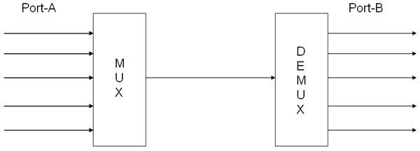
- Assume that we have two ports (Port A and Port B) and the communication between them is through a single datapath. Consider that there are 5 input channels in Port A and 5 corresponding channels in Port B to receive the signal from each of the channels from Port A.
- Now since I said that there is only 1 datapath between the two ports, electronically the data from the 5 channels is sent through the single datapath by the process called multiplexing.
This essentially means (in layman terms) that the data from a channel is sent through the data path and the corresponding receiver channel receives the signal in the output side.
- On finishing this transmission, the next input channel is selected and the data signal from this channel is sent to its corresponding receiver channel.
Fig. 1: MUX-DEMUX pair transmitting data from 5 channels of Port A to 5 channels of Port B
So what is changing the input channel and the corresponding output channel?
How are the channels selected?
You may wonder how the demultiplexer chooses the output port corresponding to the input port chosen by the Multiplexer.
- When the multiplexer chooses a particular input channel for sending that channel’s data, it not only sends the data but also a set of codes called “select lines.”
- This contains the information to tell the demultiplexer that the multiplexer chose that particular input channel. Thus the demux selects the output channel as per the select lines information.
Essentially, we know that the multiplexer is just a device and has no intelligence. Hence the mux does not generate any “select lines” code on its own.
Instead, this code is provided by the user to the mux, and based on the code, the mux chooses the input channel. This select line code again helps the demux decide which output channel it should choose.
Technically speaking…
The number of input/output lines in a de-multiplexer is as follows.
Say, the number of output channels = 2n
Then the number of select lines = n.
So while multiplexing, the MUX chooses one of the input lines as per the n-bit select code and sends the signal through the datapath.
Now the demultiplexer has received an input and it should select a particular channel for the outputting this signal. This selection is done by using the “select code.”
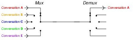
Fig. 2: GIF showing the action of MUX-DEMUX pair.
For choosing a particular output channel the corresponding select code should be provided to the demux.
Sample Demux
The above mentioned example of having 5 output channels for the demux can be realized as follows.
Since the number of channels = 5, the number of select bits = 3
(As 2^3 = 8 > 5, whereas if we consider select bits = 2, then 2^2 = 4 < 5)
Consider the output channels as C1, C2, …C5
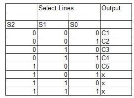
Here you can see that based on the bits S2, S1, S0 the output channel is selected.
Since we have only 5 channels, the remaining 3 combinations of the select bits is assigned as “don’t care” elements. We can either assign the demux to choose any particular channel if any of these 3 combinations occur or we can use these combinations as RESET codes so that when the demux receives one it resets the demux, thereby skipping one data input cycle (no output for that particular cycle)
Worth understanding…
- From the above table the Demux is designed by obtaining the Boolean Expression for the output channels. This is generally done using Karnaugh Map (K-Maps)
- Note that the MUX-DEMUX pair works only as a simple routing device. It doesn’t manipulate the data signal that is being sent through it.
- At any given instant of time, only one input channel can send data to only one output channel.
A MUX-DEMUX pair is different from an ENCODER-DECODER pair in that;
- The latter modulates the data signal so that an “n” bit data is sent through a channel with bits less than “n” and then on reaching the receiver side the decoder once again demodulates the data signal into an “n” bit signal
- The MUX-DEMUX pair just sends the data as it is without manipulating any of its parameters.
References
References
Multiplexing/Demultiplexing, https://www.cs.umd.edu/~shankar/417-F01/Slides/chapter3a/sld005.htm
TCP Multiplexing and Demultiplexing using Port numbers, https://www.omnisecu.com/tcpip/tcp-port-numbers.htm
Multiplexing and Demultiplexing Network Applications, https://210.43.128.116/jsjwl/net/kurose/transport/fund.html