Flow Chart for Finite Element Analysis – Overall Steps for FEA, FEM or CAE
What is Finite Element Analysis?
The finite element analysis (FEA) or FEM is a problem solving approach for the practical (engineering) problems. The problems are first converted to matrix and partial differential equation forms. Eventually the partial differential and integral equations are being solved to reach the solution of the problem. The volume of the equations to be solved is usually so large that arriving solution without using computer is practically impossible. And, that’s why the need of different FEA packages is felt. There are many FEA packages available for different applications. Some popular FEA packages are Pro Mechanica, Ansys, Nastran, and Gambit etc.
Flow Chart for Finite Element Analysis
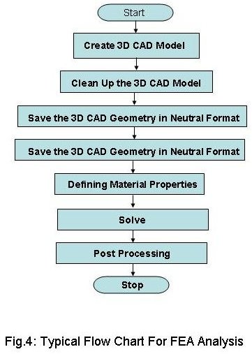
Typically a complete finite element analysis flow chart should have the steps, for the shake of easy discussions I am writing the steps in bullet points form instead of flow chart form:
-
Create 3D CAD Model: Use any of the 3D CAD modeling tools like ProE, Catia, and solid Edge etc. for creating the 3D geometry of the part/assembly of which you want to perform FEA.
-
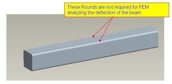
Clean Up the 3D CAD Model: Some features of the 3D CAD geometry may not be that important for the FEA but increase the complexity of meshing drastically; you need to remove those features of the CAD model. For example, if you need to analyze the deflection of the below bar
You better remove the rounds in order to avoid complexity while meshing.
- Save the 3D CAD Geometry in Neutral Format: Save the 3D CAD geometry in neutral format like IGES, STEP etc. Though some of the FEA packages allow importing the CAD geometry directly from some of the 3D CAD packages. For example, the ProE geometry can be directly imported to Ansys.
- Importing 3D CAD geometry to FEA Package: Start the FEA package and import the CAD geometry into the FEA package.
- Defining Material Properties: You need to tell the FEA package which material you are using for the part. By this process you have to tell modulus of elasticity, poissions ratio and all other necessary properties require for the FEA.
- Meshing: Meshing is a critical operation in FEA. In this operation, the CAD geometry is divided into large numbers of small pieces. The small pieces are called mesh. The analysis accuracy and duration depends on the mesh size and orientations. With the increase in mesh size, the finite element analysis speed increase but the accuracy decrease.
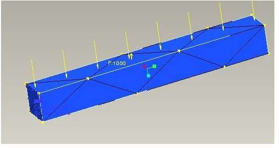
- Defining Boundary Condition: You have to tell the FEA package where you want to apply loads and where you want to rest the part/assemble (constraints).
- Solve: In this step you tell the FEA package to solve the problem for the defined material properties, boundary conditions and mesh size.
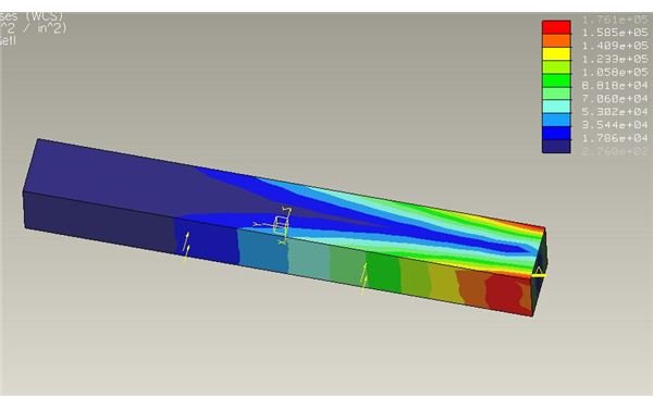
- Post Processing: You view the results of the solution in this step. The result can be viewed in various formats: graph, value, animation etc.
Conclusion
The flow chart for finite element analysis (FEA) or FEM or CAE discussed here is typical overview of a FEA. After viewing the results, all or some of the steps may be performed again in order to get the desired result.