UG Tutorial – Unigraphics Expressions, Example and Application of the UGS expressions
The concept of expressions in Unigraphics is equivalent to the parameters and relations of ProE or somewhat similar to the adding formulas in MS Excel. In UGS expressions are used for controlling the relations between the features of a part and the parts of an assembly. Before going to the example, let’s see the different types of expressions available in UG:
- Software Expressions: These UG expressions will be created by the software automatically during some of operations. For example if you create a sketch of a rectangle and dimension it, UGS will create as many parameter as the numbers of dimensions.
- User Expressions: You will create these UG expressions as and when required according to your design requirements.
Creating UG Expressions
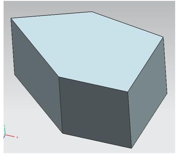
For discussing the concept we will take the example of the following pentagon block:
- Create the UG model of the block as usual extrusion: draw the sketch, give dimensions to all the five sides, and specify the height.
- Now, go to tools → expressions and you will find the expression window like below:
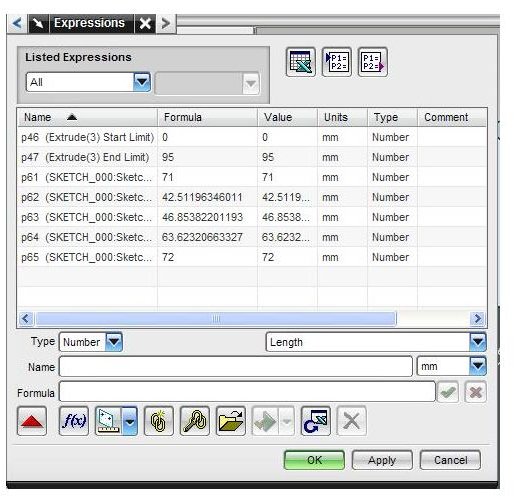
- Click the drop down list below the listed expressions and set it to all and you will see the already available expressions in the window, these expressions are Software expressions.
- There will be total of seven software expressions available, five will be for the five sides dimensions and two for the height of the pentagon.
- You can rename the software expressions, for that click on a expression and change the name from the Name field of the dialog box and click apply.
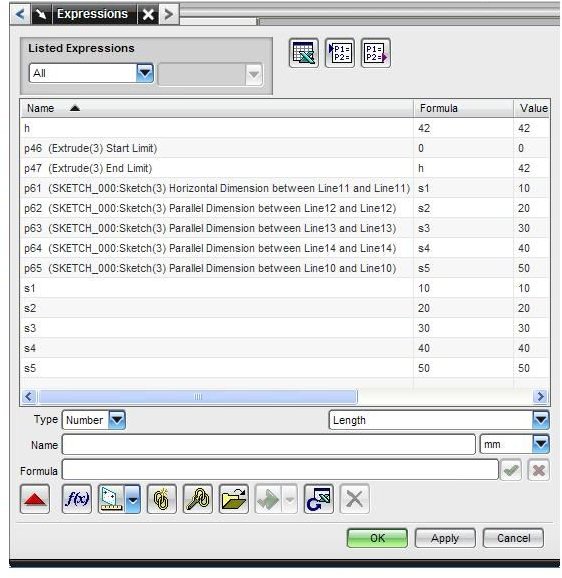
- Now, we will create six user expressions, five are for the five sides (s1, s2, s3, s4, and s5) of the pentagon and the sixth one for the height (h).
- For creating a user expression, enter suitable name in blank Name field and enter some value at the Formula field. Click Apply.
- Next, we have to relate the software expressions with the user expressions. For that, click software expressions and replace the value of it with the suitable user expression. For example, we have related the software expression p61 with the user expression s1, and p62, p63, p64, p65, p47 with s2, s3, s4, s5, and h respectively.
- So, finally the expression dialog box will look like below:
- Click on Apply and OK, the expressions dialog box will be closed.
- Now, look at the part navigator of your model tree, expand the user expressions and you will find all the user expressions are listed there. You can change the values of any of them simply by double clicking on it, editing the value and pressing the Enter. And you will see the change in your UG model.
Conclusion
This UG tutorial explained a typical example of the application of the Unigraphics expressions. After understanding the concept of UG expressions you can apply it to your mechanical design.
Related Readings
<strong>Unigraphics Tutorial – Learn the Simplest Sweep Option of UG</strong>:Three different types of sweep options are available in Unigraphics. This UG tutorial will discuss the sweep along guide option, the simplest UGS sweep option.
<strong>Unigraphics Tutorial – Know the Three UG Boolean Operation</strong>: Boolean operations are one of the distinctive features of Unigraphics. In this UG tutorial we will see how to use the Boolean operation in Unigraphics and where you can use the UGS Boolean operation.