ProE Surface Modeling Tutorial: Learn the Edit Options of Pro Engineer Surfacing
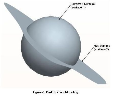
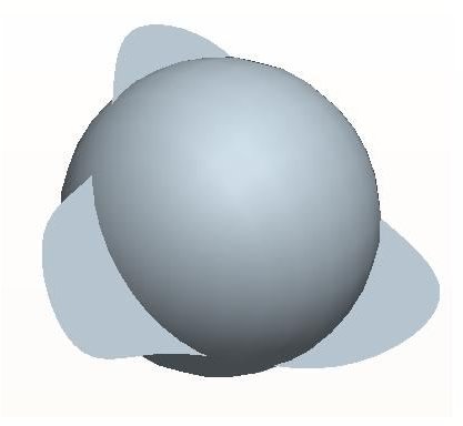
Modeling the intricate surfaces of aircraft or automobiles and generating the conceptual designs are some of the many situations where you have to use ProE surface modeling. Various edit options are used very frequently while working with the surface modeling of Pro Engineer. Five of the most useful surface modeling editing options will be discussed below and the following figure (figure-1) will be referred to in the discussions of all the edit options:
Merge
In ProE surface modeling, most of the time you will build a surface model by creating pieces of surfaces adjacent to the other. In order to convert the surface model to a solid part you have to first merge all the surfaces. For this purpose you have to use the “Merge” option.
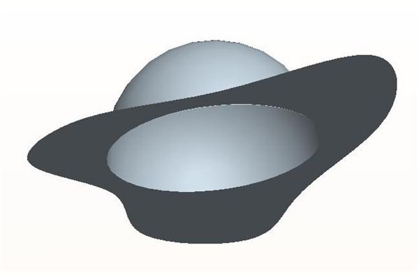
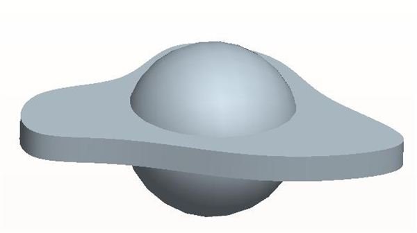
Click the “surface-1” and “surface-2” by pressing Ctrl button and then go to Edit → Merge. The Merge dashboard dialogue box will appear where you can change the directions for each of the surfaces. For our model (Figure-1) after merging it will appear like below:
Trim
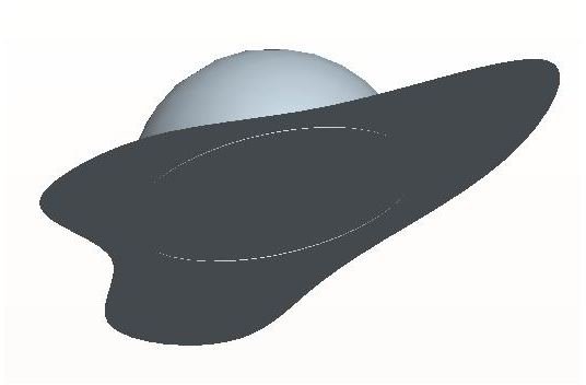
For trimming a surface by another surface curve, the two entities need to be intersected with each other. Say, we need to trim the “Surface-1” with the “Surface-2” of the Figure-1. Click the “Surface-1” and go to Edit → Trim, you will get the “trim dashboard” appear; now you need to select the “Surface-2” as the trimming surface. You can “Toggle” the side to keep. The final trimmed geometry will look like below:
Intersect
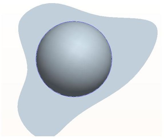
Very often you will require a curve at the intersection of two surfaces. The “Intersect” option is used for generating such curves. The curves are used for various purposes. For generating intersection curve between the “Surface-1” and Surface-2” of the Figure-1, click both the surfaces by pressing Ctrl button and go to Edit → intersect and that’s it. You will get a curve like below (the blue curve in the figure):
Offset
As the name implies, this option will help you create offset surfaces or either flat or curved surfaces. We will see how to create offset surface of the “surface-1” of the figure-1. Click the Surface-1 and go to Edit → Offset and the offset dashboard will appear, where you have to define the offset distance, type and direction. For our case by offsetting the surface-1 by 60mm we will get a surface like below:
Thicken
After capturing all the intricacies in the ProE Surface modeling you have to make it solid. For this purpose you have to use the “Thicken” editing option. For the above example (Figure-1) we will thicken the “Surface-1” and for that you have to select the Surface-1 and go to Edit → thicken, the thicken dashboard will appear, where you have to define the thickness and direction. After thickening the surface-2 by 50mm it will look like below:
Conclusion
Like Unigraphics, Solid Edge and other 3D CAD modeling packages, Pro Engineer also has surface modeling features capable of capturing intricate surface details of automobiles or aircraft. Effective usage of the ProE surface modeling edit options discussed in the ProE Tutorial will help you in generating surfaces with minute details.
Related Reading
The Simplest Command to Start ProE Surface Modeling: This ProE tutorial will give you the details about boundary blend option. We will discuss boundary blend option of pro engineer surface modeling with an example.