Pro-Mechanica Tutorial on Structural Constraints
When you apply a force then you want to see the results of the applied force in the body in terms of stress, displacements etc. The main aim of any FEA is to arrest displacement completely or partially in a predetermined way.
Displacement constraints: Go to insert>displacement constraints to open theconstraints dialogue box. Groups of constraints of similar types could be clubbed under a set. For example, say you have a circular plate with a hole at the center; now you have many options to make the geometry constraints under external loads.
Displacement Constraints
Go to insert > displacement constraints and you will be able to open the displacement constraints dialogue box.
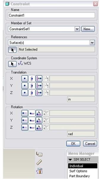
You will see the following fields in this dialogue box:
Name: You have to give a unique name to each of the constraints. Giving a meaningful name is important when you are dealing with multi-constraints and real time problems.
Member of Set: Group of constraints of similar types could be clubbed under a set. Take our previous example of a circular plate with a hole at the center. One option is to make displacement equal zero for the inner cylindrical surface, or you may think of making all the displacement constraints to zero at the outer cylindrical surface. Here you can actually apply these two constraints sets to geometry and give these two sets two different names. Now when you do the design study you will have option to select any one or both of these constraint set.
References: Here you will select the curves, points or surfaces on which you will apply different constraints.
Coordinate System: you have to select the coordinate system with respect to which you will apply the constraints by default. Change the coordinate system by clicking any other coordinate system of you choice.
Translation: You have to select a translational degree of freedom under this section. For any of the “X”,”Y” and “Z” directions you can either make the body totally fixed or you can make it totally free to move or you may specify some amount of movements. You can even make the constraints a function of coordinate. The four buttons represent these four options respectively.
In most cases we only use the first two options. If you want to specify limited movement then click on the third button of the desired direction. This will allow you to specify the magnitude of the movement.
Please note that if the situation demands any other types of coordinates other than the Cartesian coordinate system, you can select that system and the respective fields of “X”, “Y” and “Z” will also change accordingly.
Rotation: You can specify rotational degrees of freedom here. All the fields and buttons are similar to the translation, which we have just discussed.
Important note: Rotational constraints are irrelevant in the case of solid elements as the nodes of solid elements have only transitional degrees of freedom.
Symmetry Constraint: by clicking insert > symmetry constraint you will be able open the symmetry constraint dialogue box. The first two fields (name and set) are already common to you. The third field is type, you have to define the type of symmetry, and it may be either cyclic symmetry or mirror symmetry.
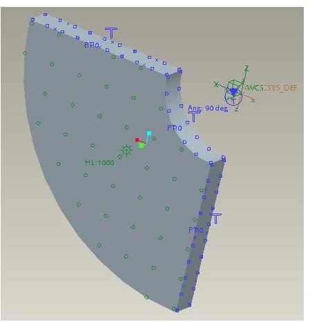
Cyclic Symmetry: You can think of using this option when the full model is circular and you can cut a certain angular sector out of it like below:
Once you choose this option in the symmetry dialogue box it will ask for first side and second side. The picture on the right was created by selecting both straight sides.
There is one more field called axis about which the model is cyclic. For the model shown in figure software could automatically detect the axis so it will be deactivated.
Mirror Symmetry: you have to cut full pro engineer mechanica model to number of equal halves and cutting surfaces will have to select as the reference surface.
Your model can include both cyclic and mirror symmetry constraints, with these limitations:
- Your proE model can include only one cyclic symmetry constraint.
- The plane defining a mirror symmetry constraint must be orthogonal to the symmetry axis for a cyclic symmetry constraint.
This post is part of the series: Pro-Mechanica Tutorial
Pro-mechanica is a FEA module of pro-engineer. If you complete reading this series and do practice as required then you will be able to do analysis using pro-mechanica, of course you should have basic knowledge of pro-engineer or other 3D cad package.
- Pro-Mechanica Tutorial Part 1: Introduction to FEA
- Pro-Mechanica Tutorial Part 2: AutoGEM & Meshing
- Pro-Mechanica Tutorial Part 3: Structural Loads
- Pro-Mechanica Tutorial Part 4: Thermal Loads
- Pro-Mechanica Tutorial Part 5: Thermal Constraints
- Pro-Mechanica Tutorial Part 6: Structural Constraints
- Pro Engineer Mechanica Tutorial Part 7: Analysis and Design Studies
- Pro-Mechanica Tutorial Part 8: Reviewing FEA Results