Pro Mechanica Tutorial on Loads Simulation using Pro Mechanica
Structural Loads
Almost all types of real life structural loads can be simulated using Pro Engineering Mechanica.
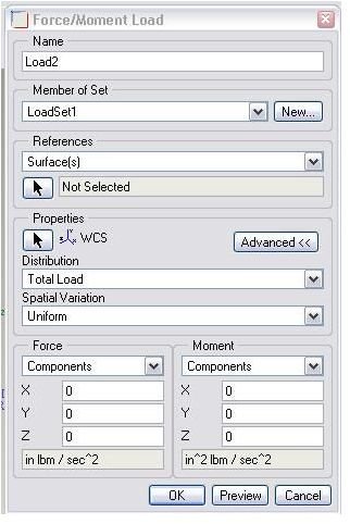
Force/moment load: Use insert>Force\moment load or click on the icon t_o_ apply this types of load. It will open the force\moment load dialogue box , which looks like below:
The dialogue box contains several fields:
Name: Give a unique name of the load you are going to define.
Member of Sets: Number of loads together makes a load set. If you are dealing with multiple numbers of loads then it is better to group them in several sets. If you do so then you will have option letter for which set/sets you want to see the FEA results or even you can compare the results from different sets. Now in this force/moment dialogue box by default it will show loadset1 to the member of set field, you can make a new load set by clicking the “new” button beside it. Another way of creating new load set is properties>load sets.
References: You have to select the reference on which you want to apply load/moment; the reference may be surface, edge/curves or points. Click on the arrow just below the field and select the desired reference and remember to click on the selection dialogue box’s “OK” option before coming back to the force/moment dialogue box. You can select multiple reference entities at a time but mechanica will create a single load for all the reference entities and not one load for each entities.
Coordinate System: At the left side of the property section of the dialogue box there is an arrow for selecting the coordinate system with respect to which all the loads and moments will be applied. By default it will be the world coordinate system (WCS).
Advanced: At right side of the property section there is advanced button, by clicking it you will get the following two fields:
Distribution: You can specify how you would like to distribute load along the selected reference entities.
If you select total load option then you have to specify the value of the sum of the loads applied to all the selected entities and ProE mechanica will equally distribute the amount of loads.
If you go with the Force per unit area/length option then you have to divide the total loads to the area or length.
There is another option available called total load at a point. In this case you have to select the point as well where you want the total loads to be acted. This will create a distributed load over the reference curve or surface which is statically equivalent to the resultant load at specified point.
You cannot select this option for 2D axisymmetric model.
Spatial Variation: Sometimes the magnitude of load may vary over the reference entities, this variation can be controlled by these options.
If your force magnitude is uniform throughout then go for uniform option.
When there is a complex variation of the magnitude then you can think of using the option function of coordinate to define this type of load. This will be discussed more later on.
There is one more way to define the magnitude variation of applied load, which is Interpolated over Entity. If you click on this option you will get a define button. Click on it in order to select the points (minimum two) where you can enter the interpolation factor.
For example if you select two points of a reference curve and at the first point if you put “1” and at the second point“2” , then at the first point the magnitude of the load will be the specified value of load (say 100) multiplied by “1” and at the second point it will be the specified load value (100) multiplied by “2” and your load distribution along the curve will gradually increase from 100 at one end to 200 at the other end. This also works similarly for surface.
Force and Moment: In this section of the force/moment load dialogue box you will be able to define the load value and direction by different options.
Components: in this option you have to enter the respective values of force/moment at “X”, “Y” and “Z” direction. Please take care about the units.
Dir Vector & Magnitude: you can specify unit vectors and magnitude to specify the force/moment. If magnitude is positive the force/moment applied to the same direction of unit vector and vice versa.
Dir Points & Magnitude: Here you can specify the direction of force/moment by “from point” and “to point” as well as the magnitude.
-
Pressure Load: Use insert>pressure load or click on the icon t_o_ apply pressure load. The pressure load dialogue box will open; it has similar fields as force/moment load which we have already discussed.
-
Bearing Loads: When there is a situation like you have a hole in a part and load transferred from a bolt to the part by the hole, then you may think of simulating the load using bearing load. Click on _insert > bearing loads._The bearing loads dialogue box is similar to force/moment load, but in the hole/pin field you have to select the bearing surface through which load will be transferred.
-
Gravity Load: Go to insert > gravity loads. The gravity load dialogue box will open. Here you need not specify the reference surface, curves or point, you just specify magnitude and that will be applied to whole assembly/part.
Centrifugal Loads: In order to apply centrifugal loads go to insert > centrifugal loads. In the centrifugal loads dialogue box you have to specify the coordinate system with respect to which the part/assembly is supposed to rotate. You also need to specify the value of angular velocity and/acceleration.
This post is part of the series: Pro-Mechanica Tutorial
Pro-mechanica is a FEA module of pro-engineer. If you complete reading this series and do practice as required then you will be able to do analysis using pro-mechanica, of course you should have basic knowledge of pro-engineer or other 3D cad package.
- Pro-Mechanica Tutorial Part 1: Introduction to FEA
- Pro-Mechanica Tutorial Part 2: AutoGEM & Meshing
- Pro-Mechanica Tutorial Part 3: Structural Loads
- Pro-Mechanica Tutorial Part 4: Thermal Loads
- Pro-Mechanica Tutorial Part 5: Thermal Constraints
- Pro-Mechanica Tutorial Part 6: Structural Constraints
- Pro Engineer Mechanica Tutorial Part 7: Analysis and Design Studies
- Pro-Mechanica Tutorial Part 8: Reviewing FEA Results